


vendor-unknown
How to Control LED's Using GY-30 Light Intensity Sensor Module Interfacing with Arduino Uno - KT697
How to Control LED's Using GY-30 Light Intensity Sensor Module Interfacing with Arduino Uno - KT697
SKU:KT697
1000 in stock
Couldn't load pickup availability
- For Bulk Order Click Here
- Need Customer Support?
- Free Delivery Above 999/-
Note: In case you receive a damaged or faulty product, please return it in the original box with all foam and packaging. Returns will not be accepted if further damage occurs due to improper packing.
If you order a product that is currently in Preorder, and the price of that item increases in the future, you will be required to pay the difference in price.
For refund/return/replacement, call us at +91 95995 94520 or email us at support@rees52.com
Delivery Time
Delivery Time
- Delivery time with the Express Shipping option is 2-3 working days, and with the Standard Shipping option is 5-6 working days. It varies based on location, reliant on courier services.
- Delivery time if the order item is on Preorder Status is 15-20 working days.
COD (Cash on Delivery)
COD (Cash on Delivery)
- For COD you have to pay extra charges of Rs 350/- before the shipment. (We will share the company QR Code, UPI ID or Account details for the same)
Product Name |
Quantity |
1 |
|
40 pieces |
|
1 |
|
1 |
|
1 |
|
6 |
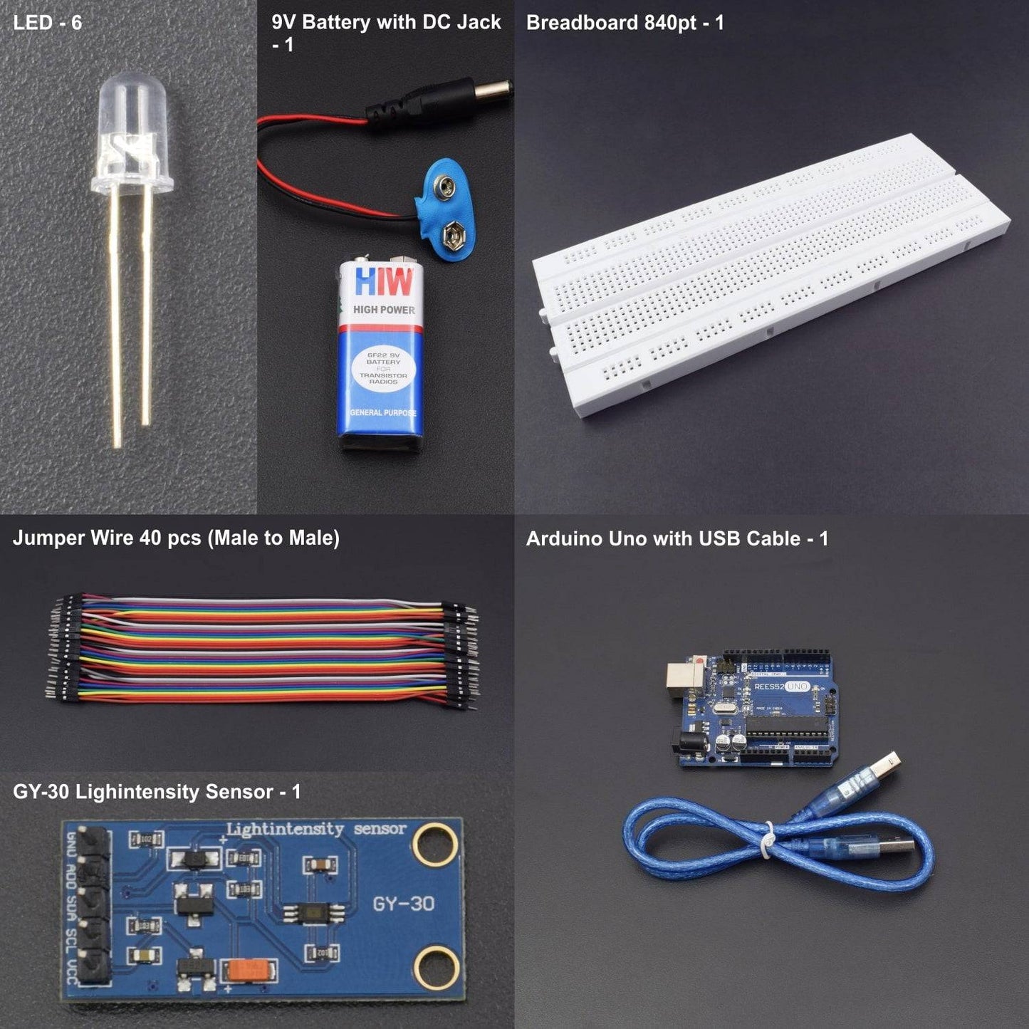
HARDWARE REQUIRED
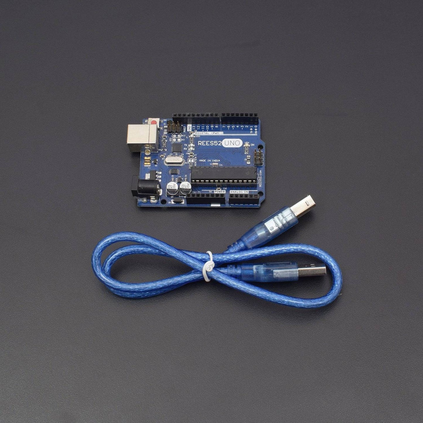
- Arduino Uno with USB cable- 1
- Breadboard 840 points – 1
- Jumper wire (male to male) – 40 pieces
- 9V Battery with DC Jack – 1
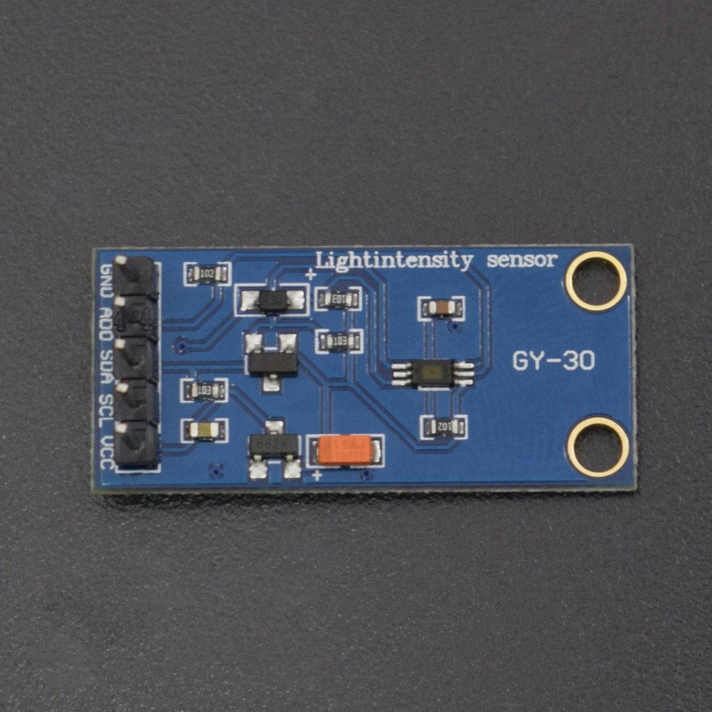
- GY-30 Light Intensity Sensor – 1
- LED - 6
SOFTWARE REQUIRED
Arduino IDE 1.8.5 (programmable platform for Arduino)
Click To Download :https://www.arduino.cc/en/Main/Software


SPECIFICATIONS
BH1750FVI Board GY-30 Light Intensity Sensor Module
- 3.3V to 5 V working DC voltage and I/O
- Wide range and high resolution is from 1- 65535 lx.
- Detection Range- 0.11 lx to 100000 lx.
- Illuminance to digital converter
- It contains 3 Measurement modes.
PIN DESCRIPTION
BH1750FVI Board GY-30 Light Intensity Sensor Module
Pin |
Name (Arduino) |
Description |
1 |
GND |
Ground (It grounds the Input and completes the circuit path) |
2 |
VCC |
3.3V (Recommended Voltage) |
3 |
SDA |
Serial Data (Serial Data used for I2C communication) |
4 |
SCL |
Serial Clock (Serial Clock used for I2C serial clock) |
5 |
Digital Pins 2 |
LED (Attached via Breadboard) |
5 |
Digital Pins 3 |
LED (Attached via Breadboard) |
5 |
Digital Pins 4 |
LED (Attached via Breadboard) |
5 |
Digital Pins 5 |
LED (Attached via Breadboard) |
.jpg)
LED Pinout


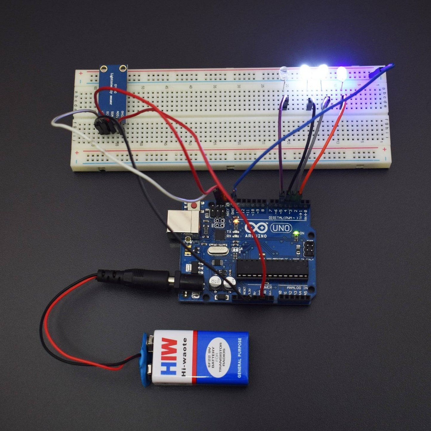
CIRCUIT CONNECTION
- The GND of Arduino is being connected with the GND pin of GY-30.
- The Digital Pin 2,3,4 and 5 of the Arduino Uno Board are being connected to the LED’s via Breadboard.
- The VCC Pin of GY-30 is being connected with 3.3V Pin of the Arduino Uno which is recommended voltage for the given circuit.
- The SDA Pin of GY-30 is connected with SDA Pin of Arduino for I2C communication.
- The SCL Pin of GY-30 is connected with SCL Pin of Arduino Uno.
- The ADDR Pin can connect with 2 devices of BH1750 with different addresses. But it depends on ADDR Pin status. But it is not included in this particular circuit.
- If ADDR = LOW , The address will be 0x23
- If ADDR = HIGH, The address will be 0x5C
NOTE: You can also connect SDA and SCL Pins of GY-30 (Light Sensor) with the Analog Pins A4 and A5 of the Arduino Uno.

LIBRARY REQUIRED
Include the Light Sensor (BH1750.h) Library:
- First, you need to Open Sketch in Arduino IDE.
- The, Click on Option Include Library.
- Click on the option Manage Libraries and enter the name of Library in the Search Bar to see if it is installed or not.
- If the Library is not installed then, click on the Library and Select the version and Click on Install Button.

CODE
Click to see code here: https://docs.google.com/document/d/e/2PACX-1vTdZvRTOqqRx7SHGIK63mTK9sb_pgiODJkKi6j7idJavMUWCA_g1NJLsauZZ4TO8lK55IGRha7xbUEj/pub?embedded=true
WORKING
Welcome to this Arduino based BH1750 Breakout Board Sensor Module which mainly consists of a serial clock Pin (SCL), Serial data pin (SDA), Power Supply (VCC), Address Pin (ADDR) and a Ground (GND) pin. The input is being transmitted towards the SDA and SCL pin ,i.e, A4 and A5 of the Arduino Uno respectively. The LED's are being attached with the Arduino Digital Pin 2, 3, 4 and 5 via Breadboard. And the Output is being displayed on the serial monitor.
Its working principle depends upon the reflecting light from a light source and measurement of illuminance is done in terms of lux. Lux is also known as luxens which is responsible for the amount of illuminance in particular light source. With the BH1750 Light Sensor intensity you can directly measure the lux. The data which is output by this sensor is directly output in Lux (Lx). When objects which are lighted they get the 1 lx luminous flux in one square meter (in general), their light intensity is 1lx. It also has three measurement modes such as:
- H-resolution with sensitivity 0.5 lux.
- H-resolution with sensitivity 1 lux.
- L-resolution with sensitivity 4 lux.
Block Diagram of GY-30:

After uploading the code
Press Ctrl+Shift+M to see the output on serial Monitor.
In the image given below you can see the Value of Light Intensity.
