

vendor-unknown
How to assemble 7 in 1 Rechargeable Solar powered DIY Robot Kit - KT670
How to assemble 7 in 1 Rechargeable Solar powered DIY Robot Kit - KT670
SKU:KT670
In stock
Couldn't load pickup availability
- For Bulk Order Click Here
- Need Customer Support?
- Free Delivery Above 999/-
Note: In case you receive a damaged or faulty product, please return it in the original box with all foam and packaging. Returns will not be accepted if further damage occurs due to improper packing.
If you order a product that is currently in Preorder, and the price of that item increases in the future, you will be required to pay the difference in price.
For refund/return/replacement, call us at +91 95995 94520 or email us at support@rees52.com
Delivery Time
Delivery Time
- Delivery time with the Express Shipping option is 2-3 working days, and with the Standard Shipping option is 5-6 working days. It varies based on location, reliant on courier services.
- Delivery time if the order item is on Preorder Status is 15-20 working days.
COD (Cash on Delivery)
COD (Cash on Delivery)
- For COD you have to pay extra charges of Rs 350/- before the shipment. (We will share the company QR Code, UPI ID or Account details for the same)
KIT INCLUDED:

Introduction:
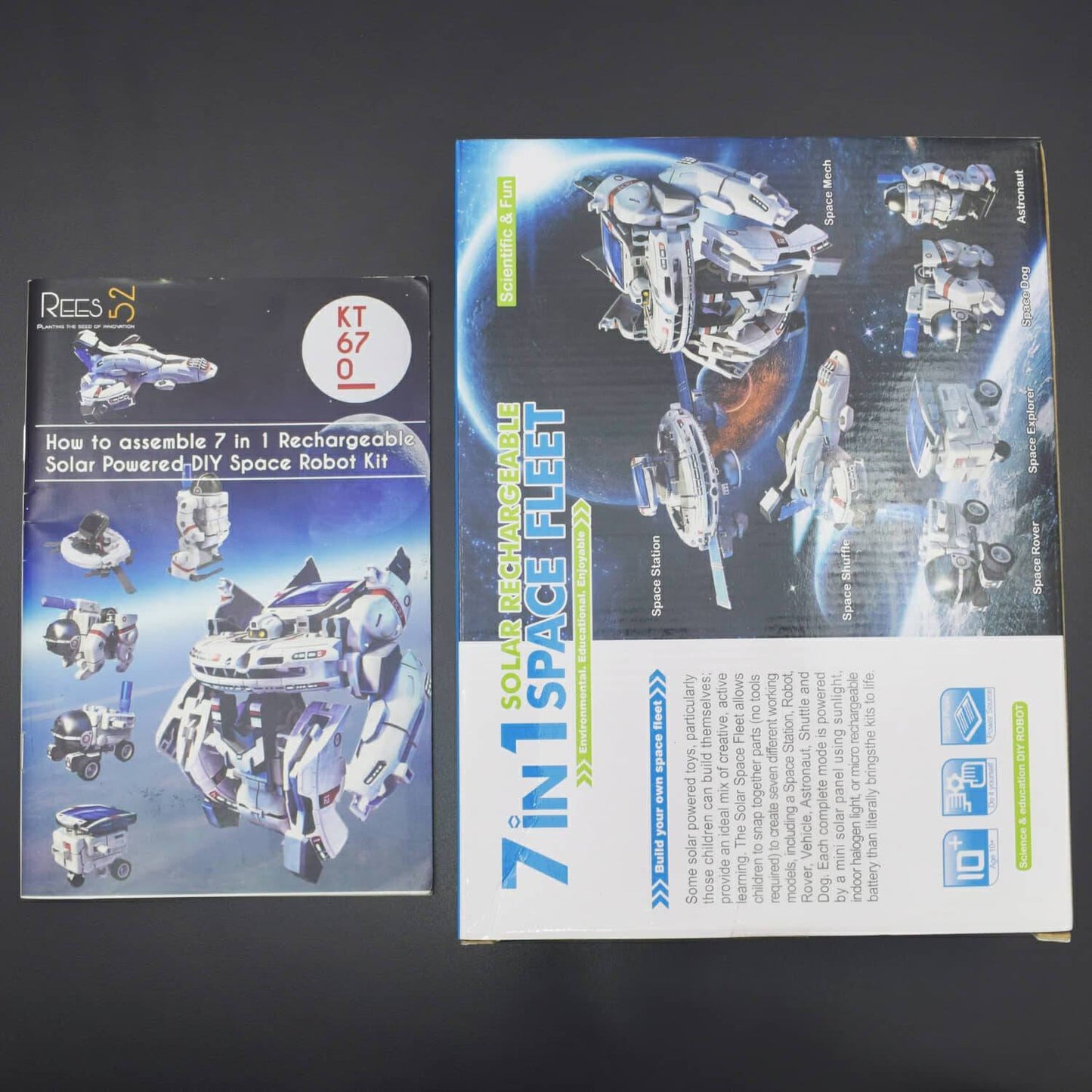
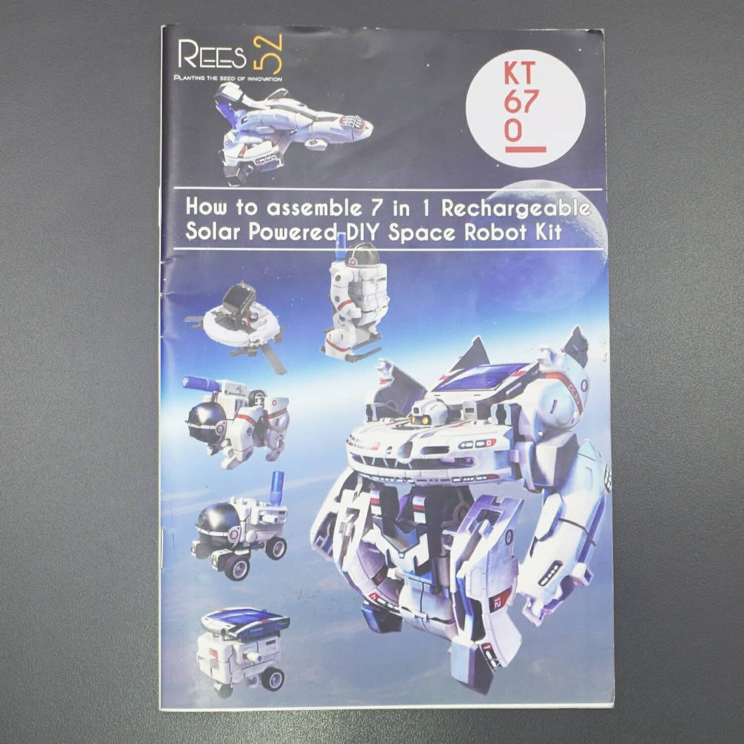
An Innovative Solar Science Kit that encourages children to exercise their sense of creativity and imagination. Build 7 different mini solar robotic toys that are fun to play with and educational. It feature all snap together plastic parts (No Screws, No Tools Required), Solar Panel and Accessories. It is incredibly easy to assemble the 7 different working models Including a Solar Space Explorer, Space Dog, Space Shuttle, Space Robot, Space Rover, Solar Space Station and Astronaut. The Solar Rechargeable Space Fleet is an innovative solar powered science kit that can transform into seven different Lunar Modules and energized via direct sunlight or micro rechargeable battery. Green energy Create 7 Different Working Models Safe Eco Friendly & Educational.
HARDWARE REQUIRED
SPECIFICATIONS
- 7 in 1 Solar Kit Rechargeable Space Fleet
- 7 different working models
- Includes an Solar Space Explorer, Space Dog, Space Shuttle, Space Robot, Space Rover, Solar Space Station and Astronaut
- Teach kids about solar energy
- Type - Art and Craft Kit
- Age - 8 Years +
- Dimension - 40 x 24 x 6 cm
BASIC ASSEMBLING
Battery Power Assembly
NOTE: To power up the module, there are two options which are being described here.
- First, we can use the micro chargeable battery to power up the module.

- Second, we can assemble the solar cell to power up the module.

NOTE: It is helpful to detach all of the plastic parts from their frame and to lay them out in front of you before starting.
- For Battery Power Assembly, first attach both batteries (AAA) with P1. Then, attach B7 with remaining component and note wire location.

- Attach P12 and P13 with the X3. Now, attach P12 (3 parts) with A7 for complete assembling as shown in image below.

- Attach B18 with the plug of the component. Secure the Plug on the side of Assembly.

Upper Gear box Assembly
- Attach Part A6 and P9 with each other as shown in image below.

- Attach Parts B8, P6 (2), P3 (2), P2 and P4 with main component A6. Now, attach the two yellow gears (P3) with Upper gear.

- Now, attach P2 and P4 with the main body of Upper gear. And, assemble Part A2 as shown in the image below.

- In this step, attach both P13 (2) and A10 (2) with each other to assemble them with upper gear body.

Lower Gear box Assembly
- In this step, attach P7 with the B15. And, attach Part B12 and A8 also note the arrow direction.

- Attach P6 and B14 with main body as shown in the image below.

- Now, you need to note the wheel Arrow direction from both Front and Rear view as shown in image below.

Gear Box Assembly
- For Gear Box Assembly, you need to adjoin both the parts for complete assembling.

- Now, test run the gear by plugging in power. You can assemble and disassemble the gear box as shown in the image below.

ASSEMBLING
Space Rover
- Attach A10, P13 and P8 with each other as shown in the image below. Now, assemble it with the Part B11.

Attach B13 with the upper gear Box and attach micro chargeable Battery. (Charging instructions are given in Basic Assembling).

Astronaut
- Attach Parts B3, B4 with A13. Now, attach B2 with themain body.

- Assemble upper and lower gear Box also note the orientation as shown in image. Attach one leg assembly to gear box.

- Now, attach A11 with main body. Attach Parts B4, A14, B3, B2 and A12 on the opposite side of the main body of astronaut.

- In this step, you can power up the module using Micro Chargeable Battery Power or the Solar Power.

Space Explorer
- In this step, assemble the landing gear by adjoining B11 and B9 and also note the position.

- Now, attach the solar module with the main body of the Solar Explorer.

Space Shuttle
- Attach the landing gear with A4. Now, attach the upper gear and A3 with the main body as shown in the image below.

- Now, attach A5 and A1 with the main body. Also, attach Part B6 and B5 with the main body as shown in the image below.

- Now, you can power up the module in two ways such as via Micro Chargeable Battery Power or the Solar Power. If you power module by solar power then, do not install B5 and B6.

Space Station
- Assemble Upper and lower gear box (note orientation as shown in image) and attach Part B13, B7 and A7 with main body as shown in image below.

- Now, you need to note the wire routing as shown in image below. And attach landing gear to the solar panel for complete assembling.

- When you use Solar Power, then attach Solar cell with main body. And attach A5 and A4 with the main body as well.

- Now, assemble the A1 and A3 with the remaining main body and repeat the same assembling procedure for opposite side as well.

- Now, you need to attach the pair of B5 and B6 with the main body. Also, you need to attach B1 with the main body for complete assembling.

- You can plug in power source of your choice to power up the module, you can use Micro Chargeable Battery or Solar Cell.

Space Dog
- Attach A14 with B2 and assemble Upper and lower gear box (note the orientation as shown in image). Also, attach the leg assembly to gear box and lastly attach A11 with the main body as shown in image below.

- Attach A13, A12 and B2 with main body and assemble opposite side as well. Also, attach B13 with main body as shown in image.

- You can power up the module using Solar Power but do not install B13 with the main body if your power source is Solar cell.

Space Mesh
- Assemble Upper and lower gear box (note orientation as shown in the image below) and attach A11 and B2 with main body.

- Attach A5 and B6 with the main body as shown in image below.

- Assemble opposite side and attach B2 and A12 with main body. And assemble other side and attach A1 and B5 with main body as shown in the image below.

- Attach B11 and B13 with main body as shown in image below.

- Attach landing gear with the main body. And also attach A3 and B6 with the main body as shown in image below.

- Attach A13 with the body and then attach that part with the battery pack of the main body.

- Attach Parts B5, A4 and A13 with each other as shown in image.

- Now, attach plug and make sure it is secure as shown in image.

- Attach the pair of B1 with the main body of the Solar Mesh as shown in the image below.

- To assemble the entire module, first you need to locate the places to be attached and then you can choose your power source to power up the module (Micro Chargeable Battery Power or Solar Cell).
