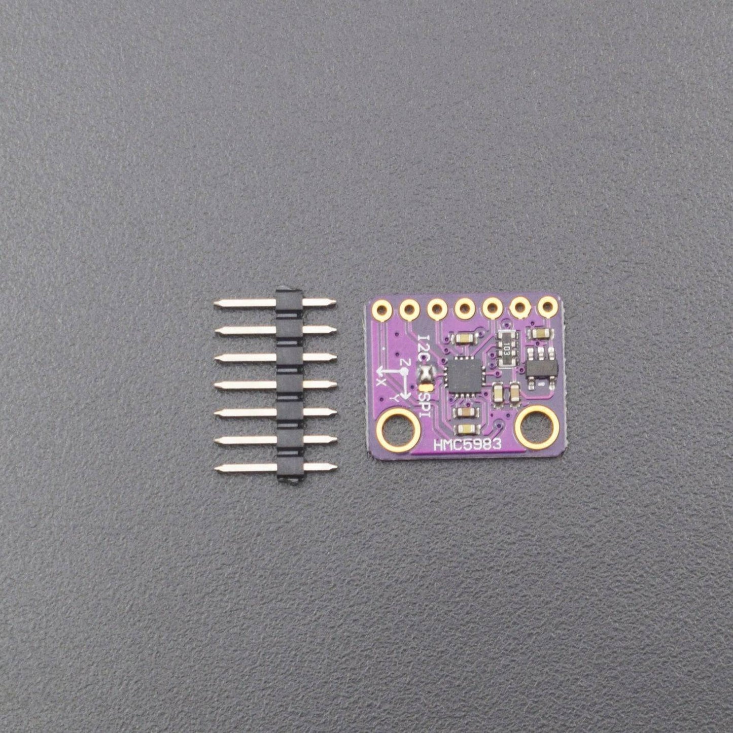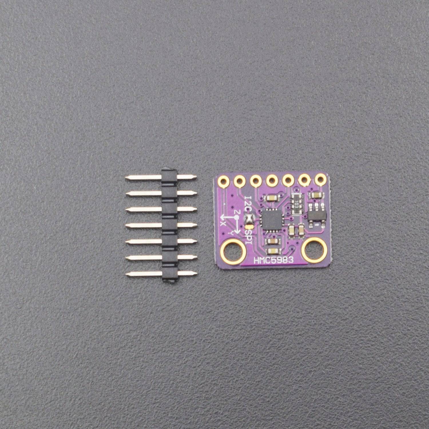


- Low Voltage Operations (2.16 to 3.6V)
- Low Power Consumption (100 μA)
- Immersion Gold Process gilded Pin interference
- HMC5983 high-precision triaxial compass magnetic field sensor with temperature compensation
- Means of communication: IIC / SPI optional
- Maximum Frequency: 220 Hz
- Accuracy Angle: 1° to 2°
- Size: 15.2 mm x 17.8 mm
Introduction
The HMC5983 is a temperature compensated three-axis integrated circuit magnetometer. The HMC5983 includes our state-of-the-art, high-resolution HMC118X series magneto resistive sensors plus an ASIC containing amplification, automatic degaussing strap drivers, offset cancellation, and a 12-bit ADC that enables 1° to 2° compass heading accuracy. The I²C or SPI serial bus allows for easy interface. This surface-mount, multi-chip module is designed for low-field magnetic sensing for applications such as automotive and personal navigation, vehicle detection, and pointing.
Features
- Low Voltage Operations (2.16 to 3.6V)
- Low Power Consumption (100 μA)
- Immersion Gold Process gilded Pin interference
- HMC5983 high-precision triaxial compass magnetic field sensor with temperature compensation
- Means of communication: IIC / SPI optional
- Maximum Frequency: 220 Hz
- Accuracy Angle: 1° to 2°
- 3-Axis Magneto resistive Sensors
- Temperature Compensated Data Output and Temperature Output
- 12-Bit ADC Coupled with Low Noise AMR Sensors Achieves 2 milli-gauss Field Resolution
- I²C (Standard, Fast, High-Speed modes) or SPI Digital Interface
- Fast 220 Hz Maximum Output Rate
- Compatible for battery powered applications
Interface GY-282 HMC5983 module with Arduino Uno
Hardware and Software required
- GY-282 HMC5983 Module
- Arduino Uno
- Arduino IDE
Hardware Connections
The GY-282 should be connected to Uno as follows:
Vin to 3.3V
Gnd to Gnd
SCK to A5
SDA to A4
Note: If the user want to communicate with this module using SPI, then the jumper at the front side of the module should be soldered for SPI.
Program for GY-282 HMC5983 Module
Upload the program given below to the Uno board after making the connections. Now open the serial monitor to see the output.
#include
#define addr 0x1E //I2C Address for The HMC5883
void setup(){
Serial.begin(9600);
Wire.begin();
Wire.beginTransmission(addr); //start talking
Wire.write(0x02); // Set the Register
Wire.write(0x00); // Tell the HMC5883 to Continuously Measure
Wire.endTransmission();
}
void loop()
{
int x,y,z; //triple axis data
//Tell the HMC what regist to begin writing data into
Wire.beginTransmission(addr);
Wire.write(0x03); //start with register 3.
Wire.endTransmission();
//Read the data.. 2 bytes for each axis.. 6 total bytes
Wire.requestFrom(addr, 6);
if(6<=Wire.available()){
x = Wire.read()<<8; //MSB x
x |= Wire.read(); //LSB x
z = Wire.read()<<8; //MSB z
z |= Wire.read(); //LSB z
y = Wire.read()<<8; //MSB y
y |= Wire.read(); //LSB y
}
// Show Values
Serial.print("X Value: ");
Serial.println(x);
Serial.print("Y Value: ");
Serial.println(y);
Serial.print("Z Value: ");
Serial.println(z);
Serial.println();
delay(500);
}

PACKAGE INCLUDED
- 1 x GY-283 module


