

vendor-unknown
Glow LED’s in Blinking Pattern using NE555 Timer IC and CD4017 IC - KT950
Glow LED’s in Blinking Pattern using NE555 Timer IC and CD4017 IC - KT950
SKU:KT950
998 in stock
Couldn't load pickup availability
- For Bulk Order Click Here
- Need Customer Support?
- Free Delivery Above 999/-
Note: In case you receive a damaged or faulty product, please return it in the original box with all foam and packaging. Returns will not be accepted if further damage occurs due to improper packing.
If you order a product that is currently in Preorder, and the price of that item increases in the future, you will be required to pay the difference in price.
For refund/return/replacement, call us at +91 95995 94520 or email us at support@rees52.com
Delivery Time
Delivery Time
- Delivery time with the Express Shipping option is 2-3 working days, and with the Standard Shipping option is 5-6 working days. It varies based on location, reliant on courier services.
- Delivery time if the order item is on Preorder Status is 15-20 working days.
COD (Cash on Delivery)
COD (Cash on Delivery)
- For COD you have to pay extra charges of Rs 350/- before the shipment. (We will share the company QR Code, UPI ID or Account details for the same)


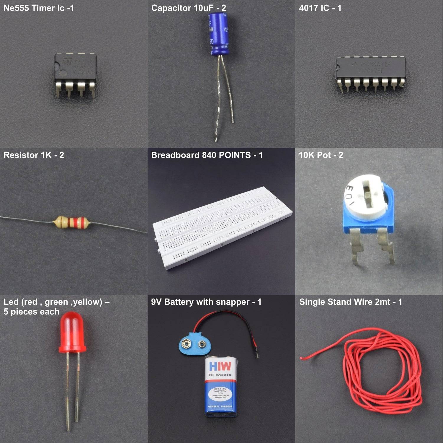
KIT INCLUDES:
- 555 Timer IC - 1
- 4017 IC - 1
- Resistor 1K - 2
- 10K Pot - 2
- Capacitor 10uF - 2
- Led (red , green ,yellow) – 5 pieces each
- Breadboard 840 POINTS - 1
- Battery 9V -1
- battery snapper – 1
- Single stand wire 2m – 1
HARDWARE REQUIRED
- 555 Timer IC - 1
- 4017 IC - 1
- Resistor 1K - 2
- 10K Pot - 2
- Capacitor 10uF - 2
- Led (red , green ,yellow) – 5 pieces each
- Breadboard 840 POINTS - 1
- Battery 9V -1
- battery snapper – 1
- Single stand wire 2m – 1
SPECIFICATIONS
Power supply - 9v from 9v battery
PIN DESCRIPTION
LED


555 TIMER IC


CD4017 IC


The importance Pins look at the table below.


1.) Pin 16 is the positive power supply and pin 8 is a ground.
The power supply range of 3 volts to 16 volts and Maximum power supply voltage at pin 1 must not much than 18 volts.
2.)Pin 13 is Clock enabled pins to controls the clock.
When it is “0” logic, the clock is enabled and the counter advances one count for each clock pulse.
When “1” logic, the clock input is stopped, and the counter does nothing even when a clock pulse arrives.
3.) Pin 14 is the clock triggers one count.
The clock pulse must be “clean”.
If they are “noisy” the counter may advance two or more times during each clock pulse.
4.) Pin 15 is the reset pin. Normally, it is “0”.
When made “1”, the counter is reset to “0”.
5.) Pins 1-7 and 9-11 are the decoded output pins.
The active count pin goes high and all others remain low.
6.) Pin 12 is Carry output, for the clock input of an additional counter or an external circuit that the count is complete.
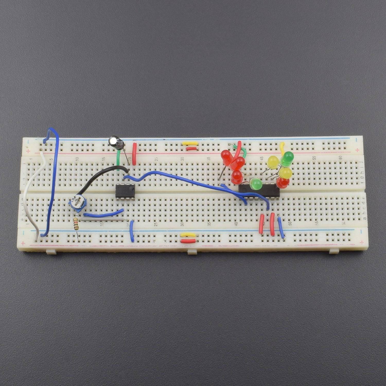
CIRCUIT DESCRIPTION


- Both IC Connected to the Breadboard.
- 4017 IC Pin No. 1,2,3,4,5,6,7,10 to connected led's positive leg and Led's negative leg is GND.
- 4017 IC Pin No. 8,13,15 are connected to the GND and Pin No. 16 connected to the positive supply.
- 4017 IC Pin No. 14 is connected to the 555 IC Pin No. 3.
- 555 Ic Pin No. 1 is GND and 555 Ic Pin No. 4 & 8 connected to the positive supply.
- 555 IC Pin No. 2 to connected 10uF capacitor positive leg and negative leg is GND.
- 555 IC Pin No. 2 to connected 10K pot 2nd (left) leg, 10K Pot Middle leg to connected 555 IC Pin No. 6 and 10K Pot 1st leg(right) to connected 1K Resistor and Resistor 2nd leg connected to the positive supply.
- 555 IC Pin No. 6 to connected 10K pot middle leg.
- Breadboard connection positive to positive and negative to the negative connection.
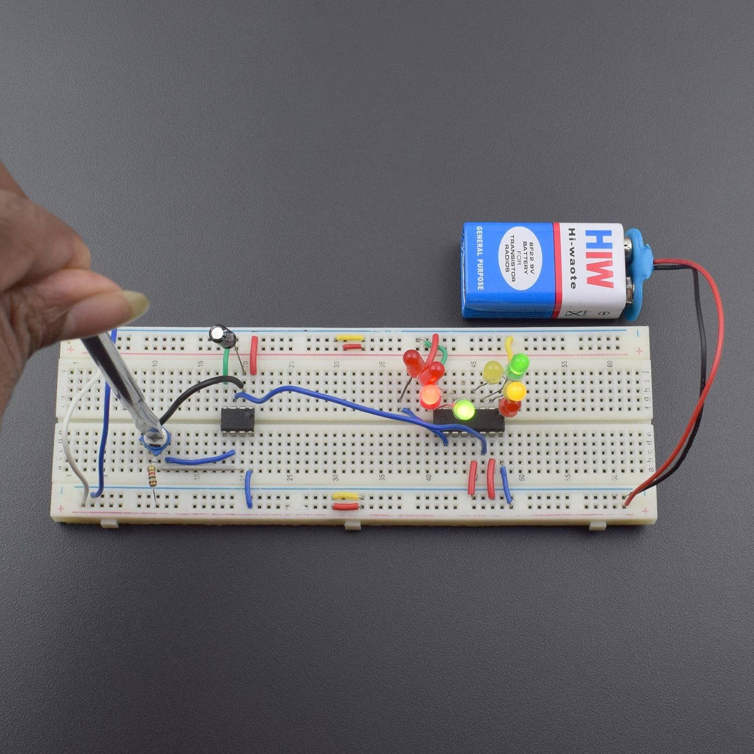
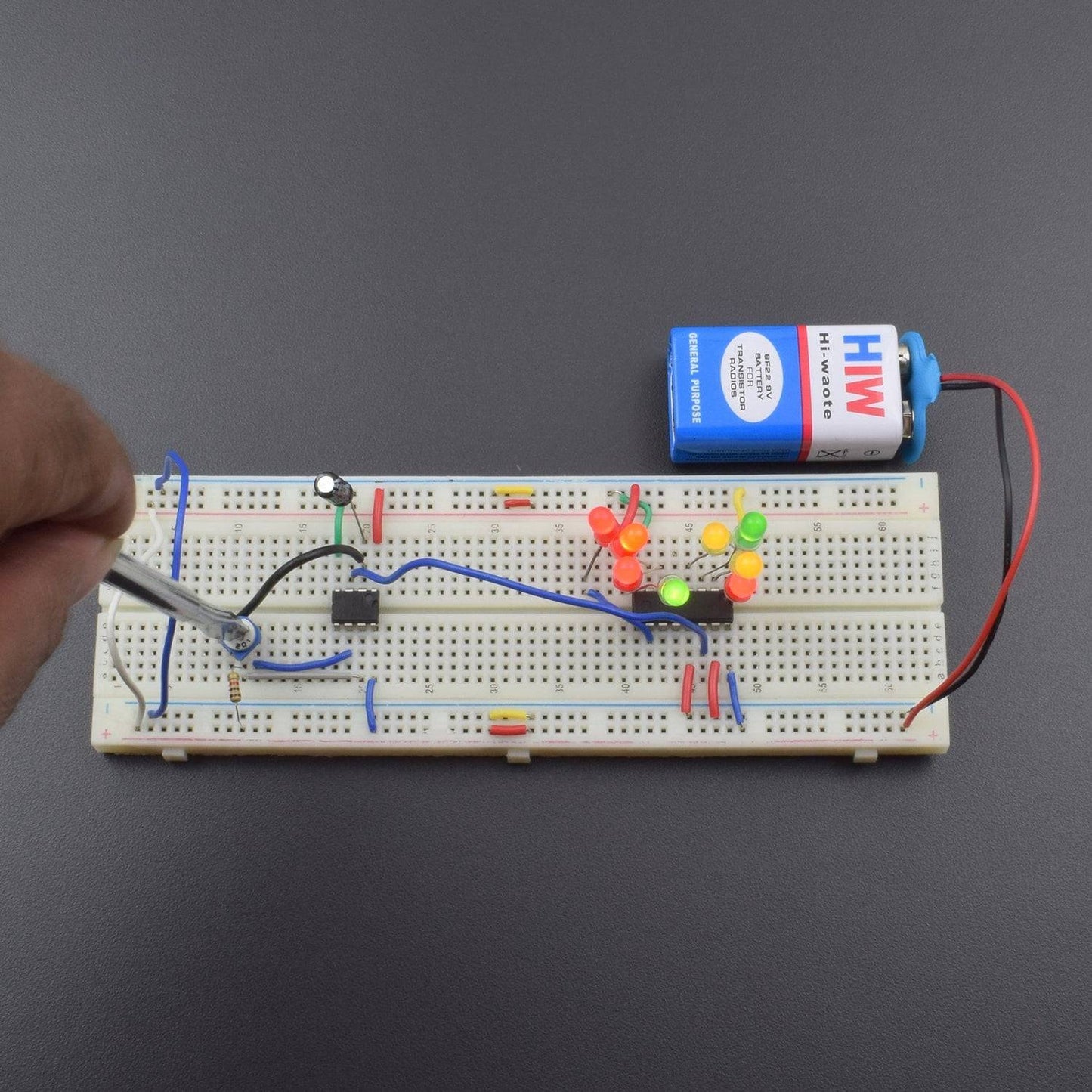
WORKING
we used 8 LEDs which are connected by the output pins of the 4017 IC according to the sequence of output, start from zero and goes up to 10 but we are using only 8 output pins as the number of LEDs are 8 and it gets the clock pulse or pulse input from the 555 timer IC in Astable mode. As the LEDs start blinking we can adjust the speed of the blinking LEDs by setting the value of resistance through a potentiometer connected in the circuit because changing the value of resistance will change the oscillation frequency of the 555 timer IC, hence the rate of the clock pulse.