


vendor-unknown
Glow an led by making Dark Sensor using LDR - KT965
Glow an led by making Dark Sensor using LDR - KT965
SKU:KT965
450 in stock
Couldn't load pickup availability
- For Bulk Order Click Here
- Need Customer Support?
- Free Delivery Above 999/-
Note: In case you receive a damaged or faulty product, please return it in the original box with all foam and packaging. Returns will not be accepted if further damage occurs due to improper packing.
For refund/return/replacement, call us at +91 95995 94520 or email us at support@rees52.com
Delivery Time
Delivery Time
- Delivery time with the Express Shipping option is 2-3 working days, and with the Standard Shipping option is 5-6 working days. It varies based on location, reliant on courier services.
- Delivery time if the order item is on Preorder Status is 15-20 working days.
COD (Cash on Delivery)
COD (Cash on Delivery)
- For COD you have to pay extra charges of Rs 350/- before the shipment. (We will share the company QR Code, UPI ID or Account details for the same)
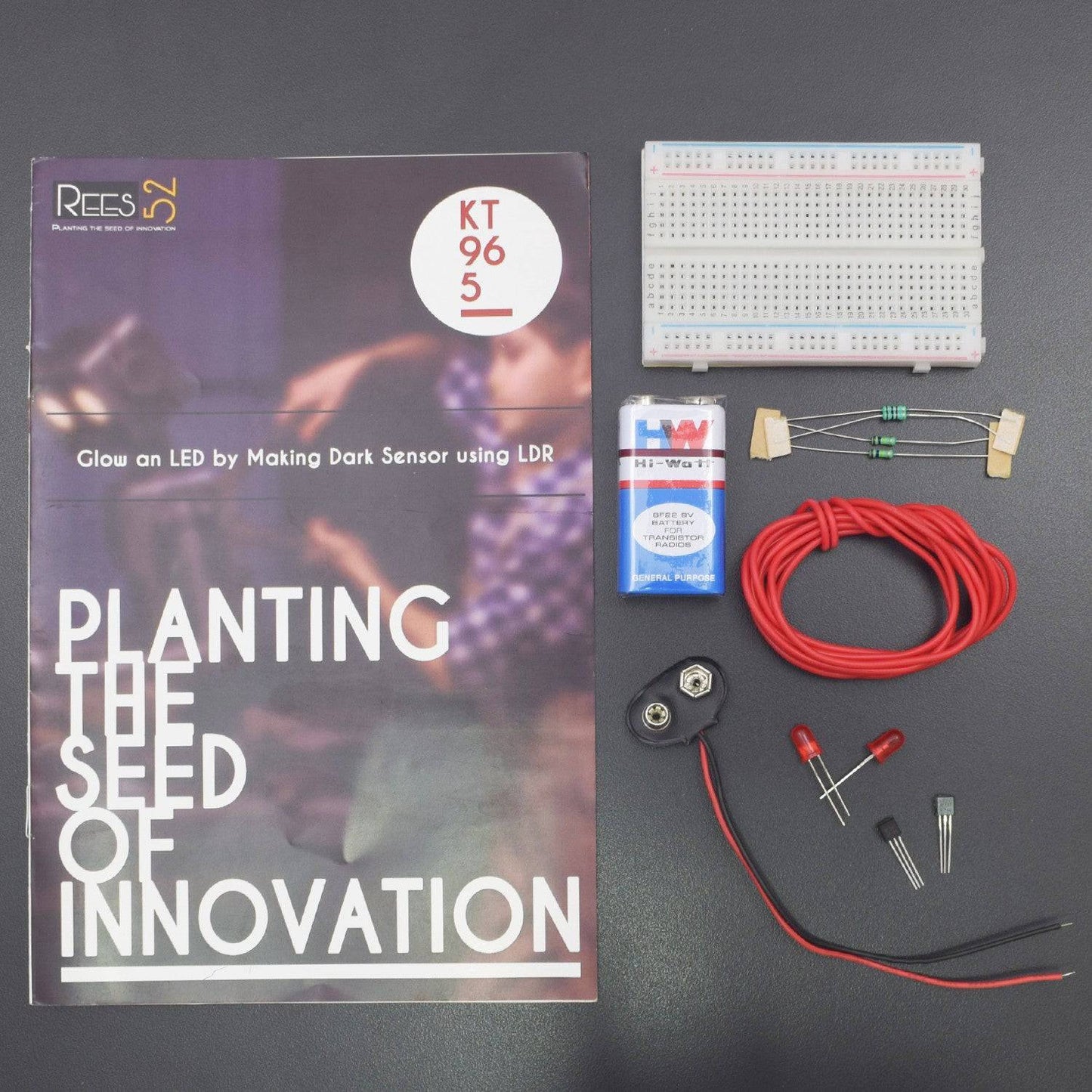

KIT INCLUDED:
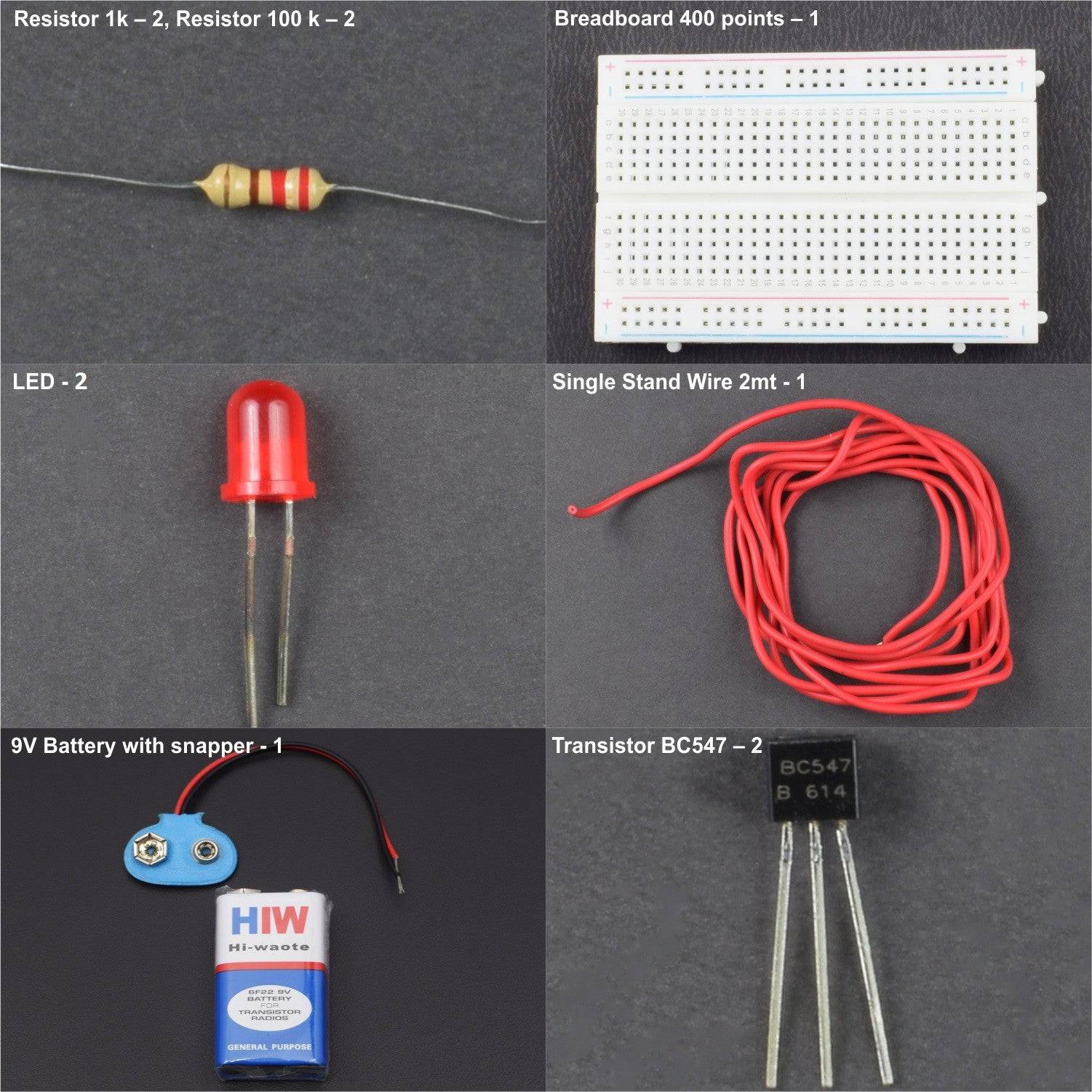
- Breadboard 400 point – 1
- 9V Battery - 1
- Snapper – 1
- Resistor 1k – 2
- Resistor 100 k – 2
- Transistor BC547 – 2
- Led – 8
- Single Stand Wire 2m – 1
HARDWARE REQUIRED
- Breadboard 400 point – 1
- 9V Battery - 1
- Snapper – 1
- Resistor 1k – 2
- Resistor 100 k – 2
- Transistor BC547 – 2
- Led – 8
- Single Stand Wire 2m – 1
PIN DESCRIPTION
LDR

LED

BC547 Transistor

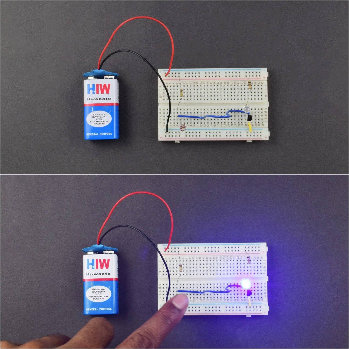
CIRCUIT DESCRIPTION

- Connect LDR one pin to the negative rail on the breadboard.
- Connect LDR pin 2 to the base of the transistor and the same rail is connected with the positive rail via a 100k resistor.
- Connect LED negative with the collector of the transistor and negative to positive rail via 1 k resistor
- Connect the emitter of the transistor to the negative rail
- Now connect the battery.
WORKING
Welcome to the LED controller project by making a dark sensor using LDR (Photodiode). The basic principle depends upon the LDR which is being described here. Automatic Dark Detector senses darkness and as light decreases and LDR meets maximum threshold resistance, the circuit automatically switches on the LED.

Dark Sensor can also be used with the variable resistor. In such cases, the sensitivity of the circuit can be adjusted with a variable resistor.
- High Resistance -> more darkness to switch on the LED.
- Low Resistance -> less darkness top switch on the LED.
Now, whenever you put a finger or hand over the LDR (Light dependent resistor), that time LED will glow.
