


vendor-unknown
Display the RGB Values on Blynk Application using RGB Led Module - KT599
Display the RGB Values on Blynk Application using RGB Led Module - KT599
SKU:KT599
1000 in stock
Couldn't load pickup availability
- For Bulk Order Click Here
- Need Customer Support?
- Free Delivery Above 999/-
Note: In case you receive a damaged or faulty product, please return it in the original box with all foam and packaging. Returns will not be accepted if further damage occurs due to improper packing.
If you order a product that is currently in Preorder, and the price of that item increases in the future, you will be required to pay the difference in price.
For refund/return/replacement, call us at +91 95995 94520 or email us at support@rees52.com
Delivery Time
Delivery Time
- Delivery time with the Express Shipping option is 2-3 working days, and with the Standard Shipping option is 5-6 working days. It varies based on location, reliant on courier services.
- Delivery time if the order item is on Preorder Status is 15-20 working days.
COD (Cash on Delivery)
COD (Cash on Delivery)
- For COD you have to pay extra charges of Rs 350/- before the shipment. (We will share the company QR Code, UPI ID or Account details for the same)


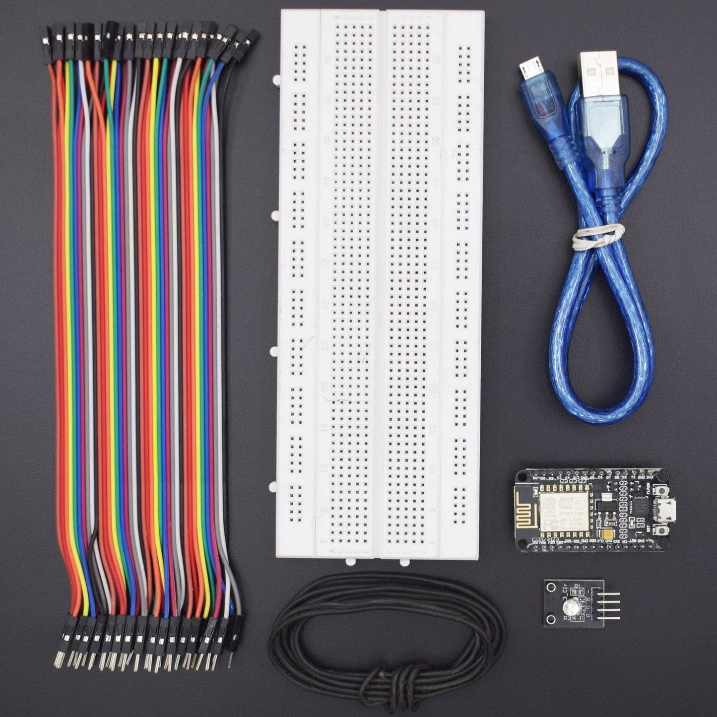
Hardware Required
- NodeMCU ESP8266 Cp2102 Wireless Module - 1
- USB Cable - 1
- RGB Led Module -1
- Jumper wire (Male to Male) – 40 pcs
- Bread Board 840 Point - 1
Introduction
In this project, we will measure the RGB Values of a Image with Blynk using RGB Colour Module. We have used Blynk App for displaying values of RGB Colour Module.
HARDWARE REQUIRED
- NodeMCU ESP8266 Cp2102 Wireless Module - 1
- USB Cable - 1
- RGB Led Module -1
- Jumper wire (Male to Male) – 40 pcs
- Bread Board 840 Point - 1
SOFTWARE REQUIRED
Arduino IDE 1.8.5 (programmable platform for Arduino)
Click To Download :https://www.arduino.cc/en/Main/Software


SPECIFICATIONS
RGB Led Module
This LED contains light emitting diodes. A red one, a green one and a blue one. Combining those into one LED will give you a RGB LED. You can all different kind of things with this LED.

NodeMCU ESP8266 CP2102 Wireless Module
ESP8266EX offers a complete and self-contained Wi-Fi networking solution; it can be used to host the application or to offload Wi-Fi networking functions from another application processor. When ESP8266EX hosts the application, it boots up directly from an external flash. In has integrated cache to improve the performance of the system in such applications.
- NodeMCU ESP-12E dev board can be connected to 5Vusing micro USB connector or VIN pin available on board.
- The I/O pins of ESP8266 communicate or input/output max 3.3V only. I.e. the pins are NOT 5V tolerant inputs.
- In case you have to interface with 5V I/O pins, you need to use level conversion system (either built yourself using resistor voltage divider or using ready to use level converters.

ESP8266 NodeMcu Installation
STEP- 1 Installing Arduino Core for NodeMCU ESP-12E Using Arduino Boards Manager
As shown in the image, Copy the .json link with latest stable release of NodeMCU package from
https://github.com/esp8266/Arduino#installing-with-boards-manager
The link should look something like this-
http://arduino.esp8266.com/stable/package_esp8266com_index.json

Step 2: Insert Link for .json NodeMCU Package Files into Arduino IDE
Paste the copied link and insert it in Arduino IDE using following sequence-
File -> Menu -> Preferences
Paste copied link into the area shown in black box in above image. Close and restart the Arduino IDE.

Step 3: Tools - Boards Manager

Tools -> Boards manager and search for ESP8266 and install the libraries/files given under heading ESP8266 by ESP community.
Restart the Arduino IDE once again.

Troubleshooting:
If you get an error as shown in image below:

Just go back to Preferences, as shown in step-2 image.
- Here, you can see the location (Marked with red box) C:UsersREES52.COMAppDataLocalArduino15preferences.txt
- Go to this location and delete all JSON Packages from Arduino15 folder. Now, Back to Board Manager and search for ESP8266 you will surely find.
Step 4: Selecting NodeMCU Board in Arduino IDE

Go to Tools -> Boards (scroll down the list of boards) - Select NodeMCU 1.0 (ESP-12EModule).
Select the Port number at which you have connected NodeMCU. Rest of the settings can be left to default values.

CIRCUIT CONNECTION
- Attach Node MCU with Breadboard.
- Connect Pin R (red) of RGB Module to Node MCU’s D1 pin.
- Connect Pin G (green) of RGB Module to Node MCU’s D2 pin.
- Connect Pin B (blue) of RGB Module to Node MCU’s D3 pin.
- Connect Pin R (red) of RGB Module to Node MCU’s D0 pin
- Connect Pin GND of RGB Module to Node MCU’s GND pin.

CODE
https://drive.google.com/open?id=1g0qInLFlfhH4HFarUacR9xx5QBE530dX
WORKING
Welcome to the NodeMCU Based Color Display Project which consists of RGB LED, Breadboard Power Supply 3.3V Module and Ethernet Shield. The basic working principle is being described here. In principle, most perceivable colors can be produced by mixing different amounts of three primary colors, and this makes it possible to produce precise dynamic color control as well. On each color scale it is possible to select 256 levels or shades of that color. If you have three primary colors and each one can have 256 different shades, then by mixing them together you can mathematically generate 16.7 million different colors. 255 x 255 x 255 = 16,581,375.
- To connect with Blynk Application. First, you need to create a new project An AUTH token will be sent to your registered Email ID which you need to note down. You need to insert the key in the given code


- Open the Widget Box and select the zeRGBa widget option from the Dropdown list.


- Click on the plus icon and select ZeRGBa
- Define the pins in our case gpio5 (d1),gpio4(d2),gpio0(d3).
- Since our is common cathode we need to define the PWM reverse
- Change the min to 0
- Max to 255

- Upload code and run the Blynk App Project. If the code is correct, the device is shown online.
- App is ready now using the authentication token we need to change the code
- After uploading, press the play button in your Blynk app. If all went well you can now slide to different colors to control the LED.