


vendor-unknown
Display the Magnetic Field value on 20*4 LCD using Linear Hall Magnetic Module - KT620
Display the Magnetic Field value on 20*4 LCD using Linear Hall Magnetic Module - KT620
SKU:KT620
999 in stock
Couldn't load pickup availability
- For Bulk Order Click Here
- Need Customer Support?
- Free Delivery Above 999/-
Note: In case you receive a damaged or faulty product, please return it in the original box with all foam and packaging. Returns will not be accepted if further damage occurs due to improper packing.
If you order a product that is currently in Preorder, and the price of that item increases in the future, you will be required to pay the difference in price.
For refund/return/replacement, call us at +91 95995 94520 or email us at support@rees52.com
Delivery Time
Delivery Time
- Delivery time with the Express Shipping option is 2-3 working days, and with the Standard Shipping option is 5-6 working days. It varies based on location, reliant on courier services.
- Delivery time if the order item is on Preorder Status is 15-20 working days.
COD (Cash on Delivery)
COD (Cash on Delivery)
- For COD you have to pay extra charges of Rs 350/- before the shipment. (We will share the company QR Code, UPI ID or Account details for the same)


Hardware Required
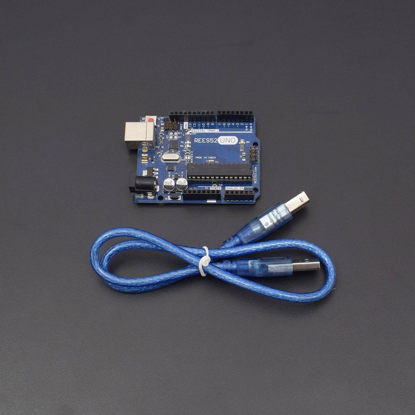
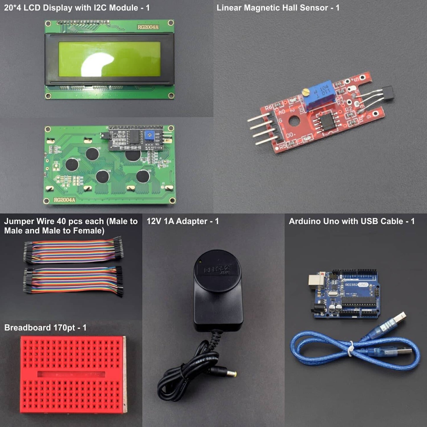
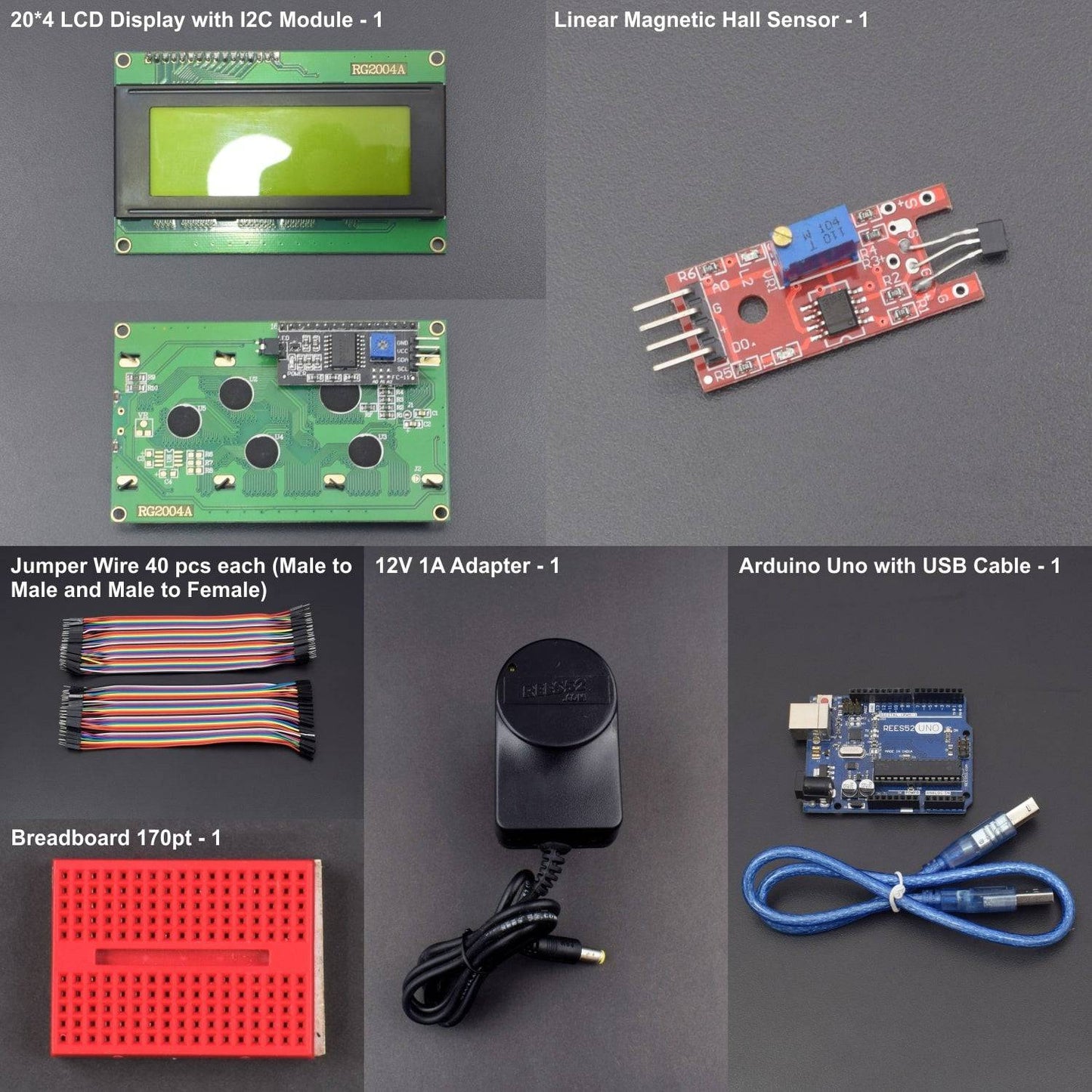
- Arduino Uno With USB Cable - 1
- Linear Magnetic Hall Sensor Module - 1
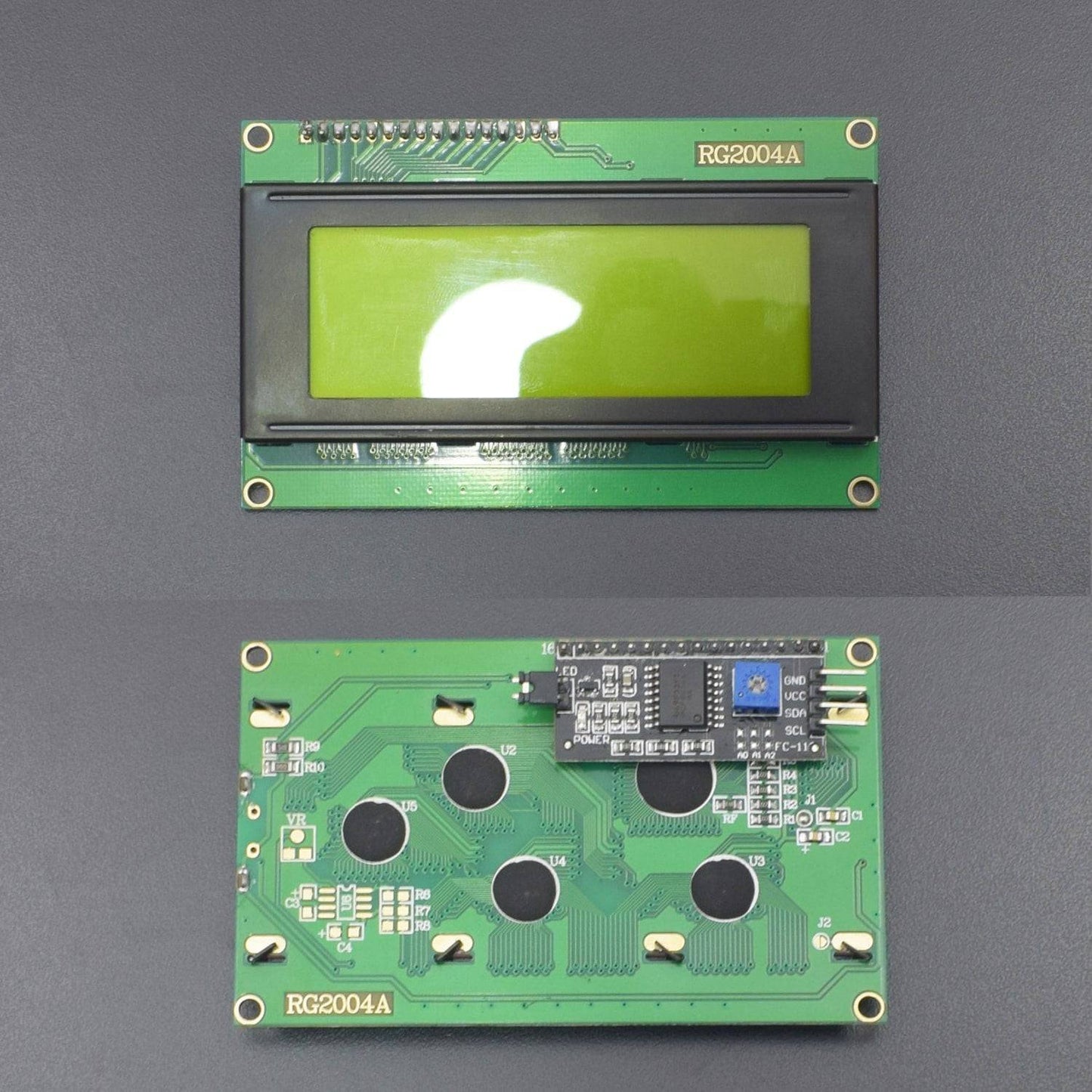
- 20*4 LCD Display With I2C Module - 1
- 12V 1A Adapter - 1
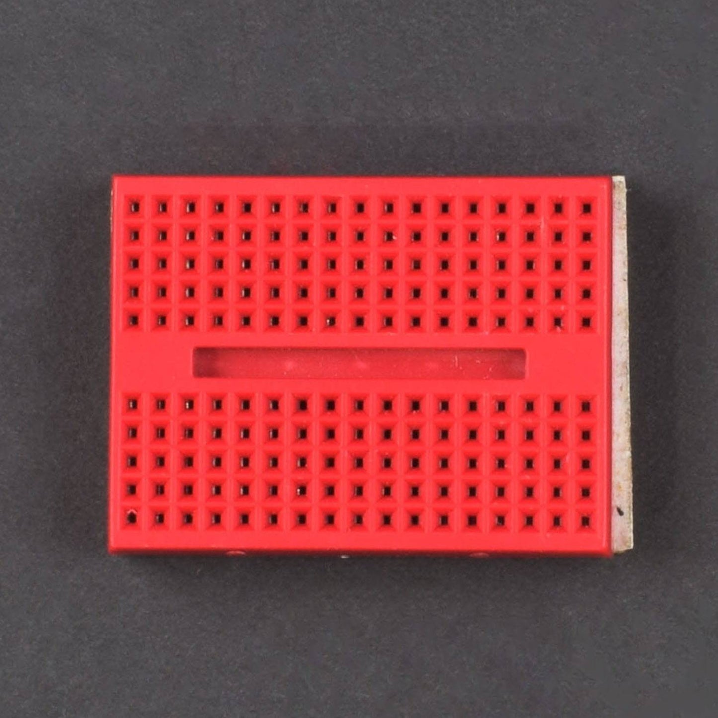
- 170 Point Bread Board - 1
- Jumper Wire (male to male) - 40 pcs
- Jumper Wire (male to female) - 40 pcs
Introduction
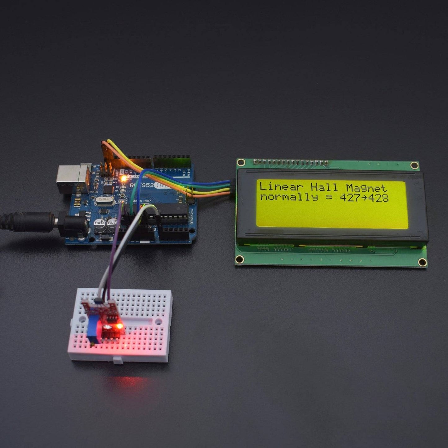
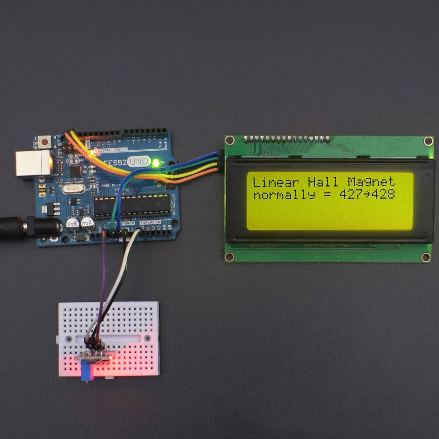
In this project, we have used Linear Hall to know about the specific magnetic field around it and display the values on LCD.
HARDWARE REQUIRED
- Arduino Uno With USB Cable - 1
- Linear Magnetic Hall Sensor Module - 1
- 20*4 LCD Display With I2C Module - 1
- 12V 1A Adapter - 1
- 170 Point Bread Board - 1
- Jumper Wire (male to male) - 40 pcs
- Jumper Wire (male to female) - 40 pcs
SOFTWARE REQUIRED
Arduino IDE 1.8.5 (programmable platform for Arduino)
Click To Download: https://www.arduino.cc/en/Main/Software


SPECIFICATIONS
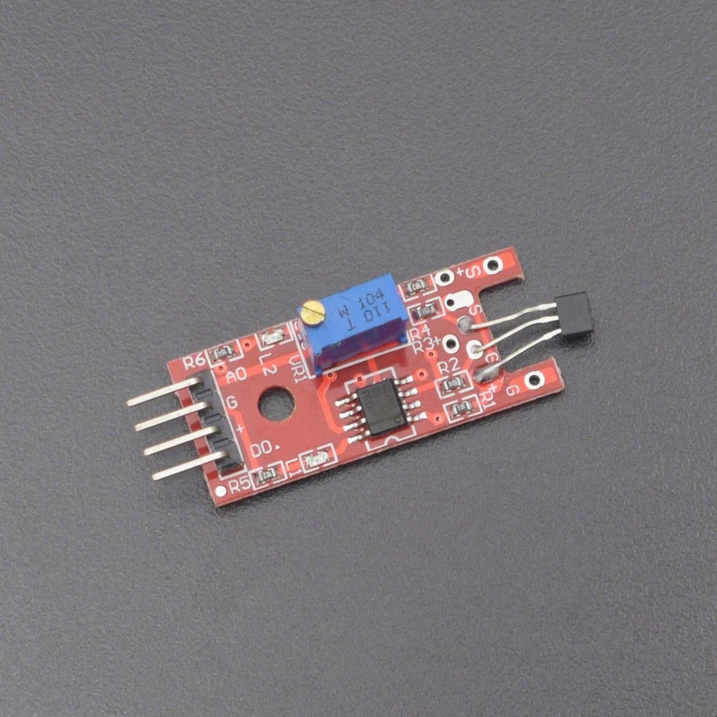
Linear Magnetic Hall Sensor Module
This sensor produces a voltage when placed into a magnetic field. The voltage can be used to control your Arduino.
It is an analog sensor which means it can read out the value of the magnetic field.
- Has the single signal output instructions.
- Effective signal output for low level.
- Sensitivity adjustable pure tone.
- Have the field cuts have signal output.

Arduino Uno

CIRCUIT CONNECTION
- Connect GND of Arduino Uno with Breadboard for further GND connections.
- Connect Pin 5V of Arduino Uno with Breadboard for further 5V power supply connections.
- Connect GND of Linear Hall Module with GND of Arduino Uno.
- Connect VCC of Linear Hall with Pin 3.3V of Arduino Uno.
- Connect Pin A0 of Linear Hall with Analog Pin A0 of Arduino Uno.
- Connect 20*4 LCD with I2C GND pin to Arduino Uno’s GND pin.
- Connect 20*4 LCD with I2C VCC pin to Arduino Uno’s 5V pin.
- Connect 20*4 LCD with I2C SDA pin to Arduino Uno’s SDA pin.
- Connect 20*4 LCD with I2C SCL pin to Arduino Uno’s SCL pin.

CODE
https://drive.google.com/open?id=1RzuevoPmDtQ6-sgffUQ6W0DJpzXyl0Fx
WORKING
Welcome to the Arduino Based Project which consists of Linear Hall Module and 1602 LCD. The basic working principle of the module is being described here. The effect is seen when a conductor is passed through a uniform magnetic field. The natural electron drift of the charge carriers causes the magnetic field to apply a Lorentz force to these charge carriers. The result is what is seen as charge separation, with a buildup of either positive or negative charges on the bottom or on the top of the plate. A hall sensor is a kind of magnetic field sensor based on the effect. Electricity carried through a conductor will produce a magnetic field that varies with current, and a Hall sensor can be used to measure the current without interrupting the circuit. Mostly, the sensor is integrated with a permanent magnet that surrounds the conductor to be measured. Here, we have used LCD to print the values of Module on LCD Display.
