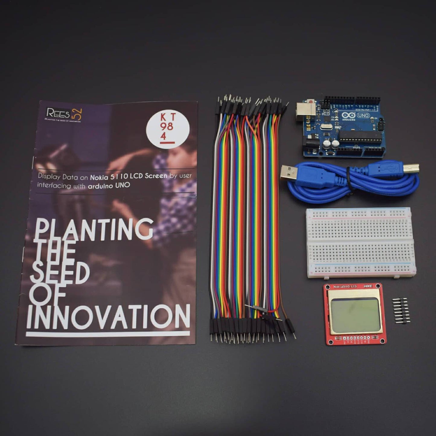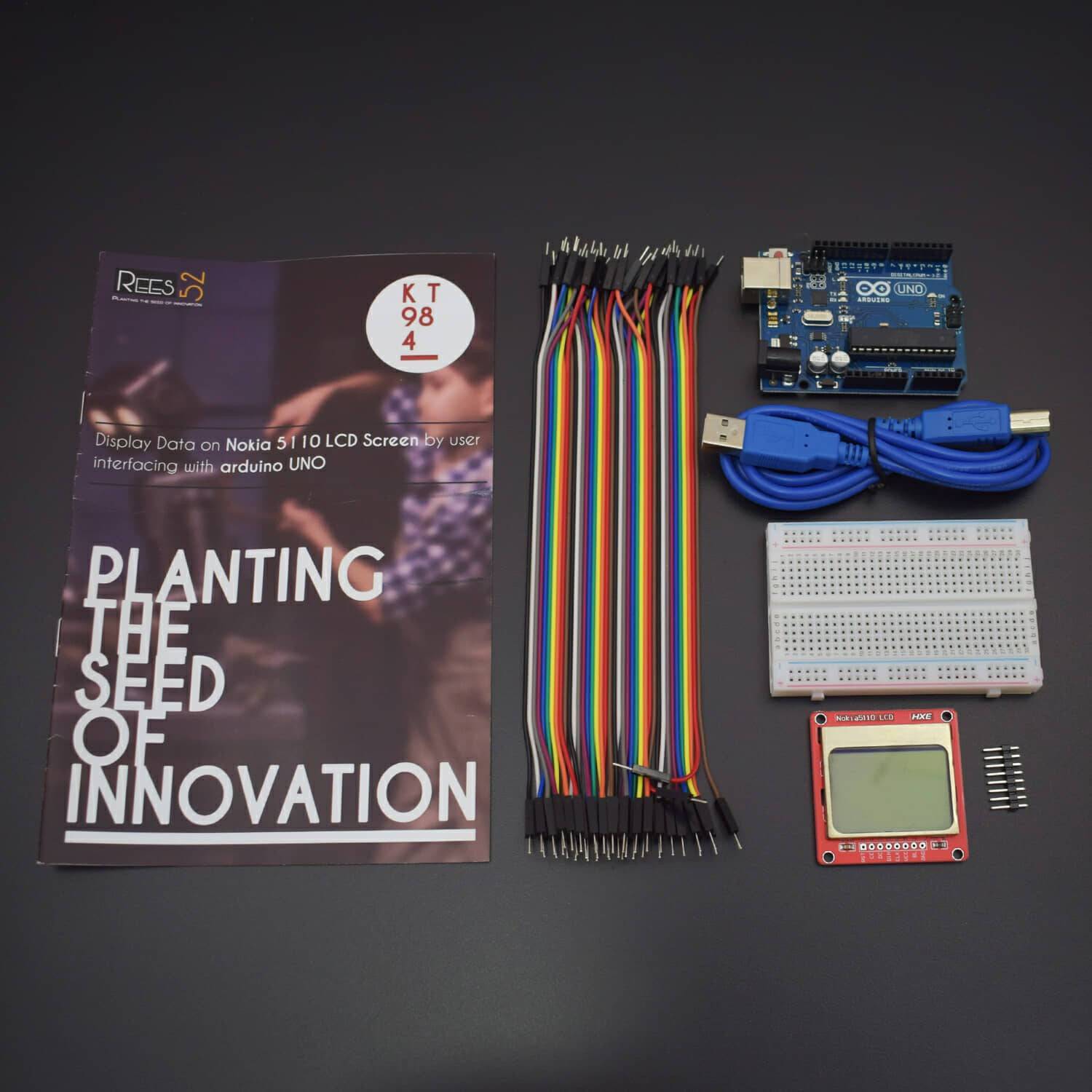

In this Tutorial, we will Test a Nokia 5110 LCD Screen Interfacing by Arduino Uno. We will display the data entered on the serial monitor and display it on the LCD screen.
PACKAGE INCLUDED:
- Arduino UNO with USB cable - 1
- Jumper wires (male to male) - 40 pieces
- Nokia 5110 Lcd Screen - 1
- Breadboard 400 points - 1
we will Test a Nokia 5110 LCD Screen Interfacing by Arduino Uno. We will display the data entered on the serial monitor and display it on the LCD screen.
The Nokia 5110 is a basic graphic LCD screen for lots of applications. It was originally intended to be used as a cell phone screen. This one is mounted on an easy to solder PCB.
It uses the PCD8544 controller, which is the same used in the Nokia 3310 LCD. The PCD8544 is a low power CMOS LCD controller/driver, designed to drive a graphic display of 48 rows and 84 columns. All necessary functions for the display are provided in a single chip, including on-chip generation of LCD supply and bias voltages, resulting in a minimum of external components and low power consumption. The PCD8544 interfaces to microcontrollers through a serial bus interface.
Note: There may be small blemishes on these screens as they are surplus.
Note: Your screen may or may not have a diode on the PCB. It does not affect performance
HARDWARE REQUIRED
- Arduino UNO with USB cable - 1
- Jumper wires (male to male) - 40 pieces
- Nokia 5110 Lcd Screen - 1
- Breadboard 400 points - 1
SOFTWARE REQUIRED
Arduino IDE ( Programmable platform for Arduino)
You can download the software from this link: https://www.arduino.cc/en/Main/Software
LIBRARY REQUIRED
- Open your Arduino IDE
- Before uploading the code you need a Library If not exist then Open IDE -> SKETCH -> MANAGE LIBRARY -> ADD LIBRARY ->search FOR SPI -> INSTALL IT
SPI (Serial Peripheral Interface) – An SPI like Interface is used to control the LCD
PIN DESCRIPTION
.jpg)
Note: Be careful at 5v.If you run it at 5V , it might have blown our LCD. You may have trouble getting it to display anything May be this will be very dim.it might display nothing at all.So, run it at 3.3V .So, be careful running it at 5 V
Pin Label |
Description |
Notes |
RST |
RESET |
ACTIVE LOW |
CE |
CHIP ENABLE |
ACTIVE LOW |
D/C |
DATA/COMMAND SELECTION |
SELECT BETWEEN COMMAND MODE (LOW) AND DATA MODE (HIGH). |
DIN |
SERIAL INPUT |
|
CLK |
CLOCK INPUT |
|
VCC |
3.3V |
SUPPLY RANGE IS BETWEEN 2.7V AND 3.3V |
LIGHT |
BACKLIGHT CONTROL |
MAXIMUM VOLTAGE SUPPLY IS 3.3V. |
GND |
GROUND |
NOTE |
|
Note: Be careful at 5v.If you run it at 5V, it might have blown our LCD. You may have trouble getting it to display anything May be this will be very dim.it might display nothing at all. So, run it at 3.3V .So, be careful running it at 5 V
|
CIRCUIT DIAGRAM

Nokia LCD |
Arduino |
RST |
DIGITAL PIN 6 |
CE |
DIGITAL PIN 7 |
D/C |
DIGITAL PIN 5 |
DIN |
DIGITAL PIN 11 |
CLK |
DIGITAL PIN 13 |
VCC |
3.3 V |
LIGHT |
DIGITAL PIN 9 |
GND |
GND |
CODE
Click to see the code or copy the link
https://drive.google.com/open?id=0BxpdhMRymue7dllJOFFvN0ZNNkU
OUTPUT

Write something and press enter. You will see that text on the NOKIA screen.


