


vendor-unknown
Dc motor controlling using single switch and 555 timer IC & 4017 IC - KT853
Dc motor controlling using single switch and 555 timer IC & 4017 IC - KT853
SKU:KT853
1000 in stock
Couldn't load pickup availability
- For Bulk Order Click Here
- Need Customer Support?
- Free Delivery Above 999/-
Note: In case you receive a damaged or faulty product, please return it in the original box with all foam and packaging. Returns will not be accepted if further damage occurs due to improper packing.
For refund/return/replacement, call us at +91 95995 94520 or email us at support@rees52.com
Delivery Time
Delivery Time
- Delivery time with the Express Shipping option is 2-3 working days, and with the Standard Shipping option is 5-6 working days. It varies based on location, reliant on courier services.
- Delivery time if the order item is on Preorder Status is 15-20 working days.
COD (Cash on Delivery)
COD (Cash on Delivery)
- For COD you have to pay extra charges of Rs 350/- before the shipment. (We will share the company QR Code, UPI ID or Account details for the same)

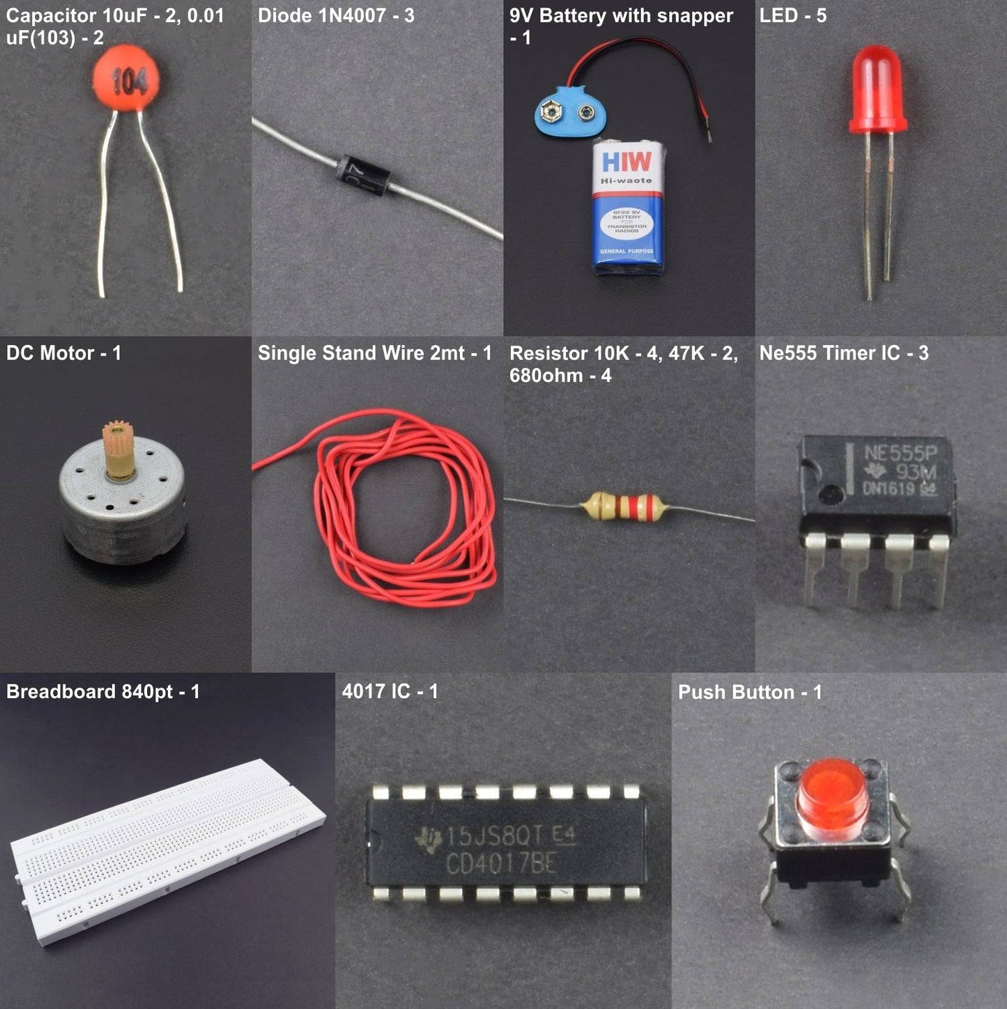
KIT INCLUDES:
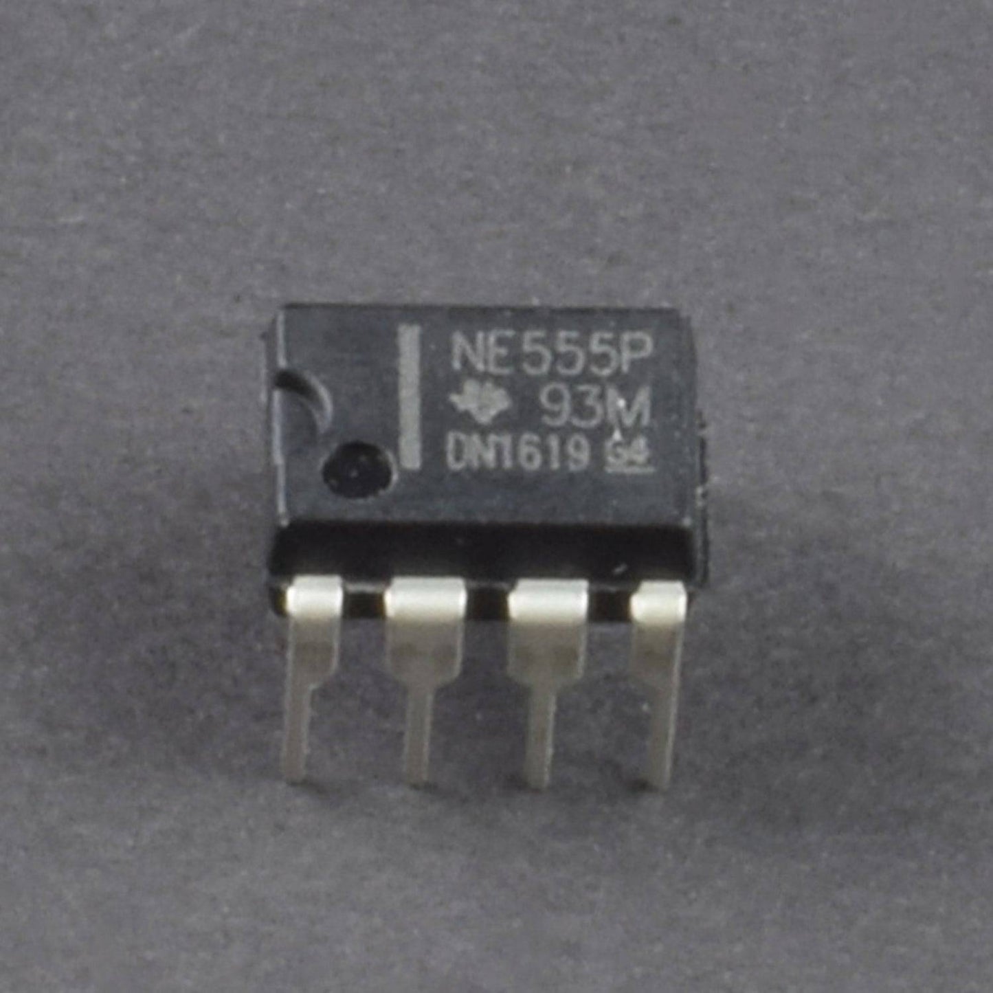
- 555 Timer IC - 3
- 4017 IC - 1
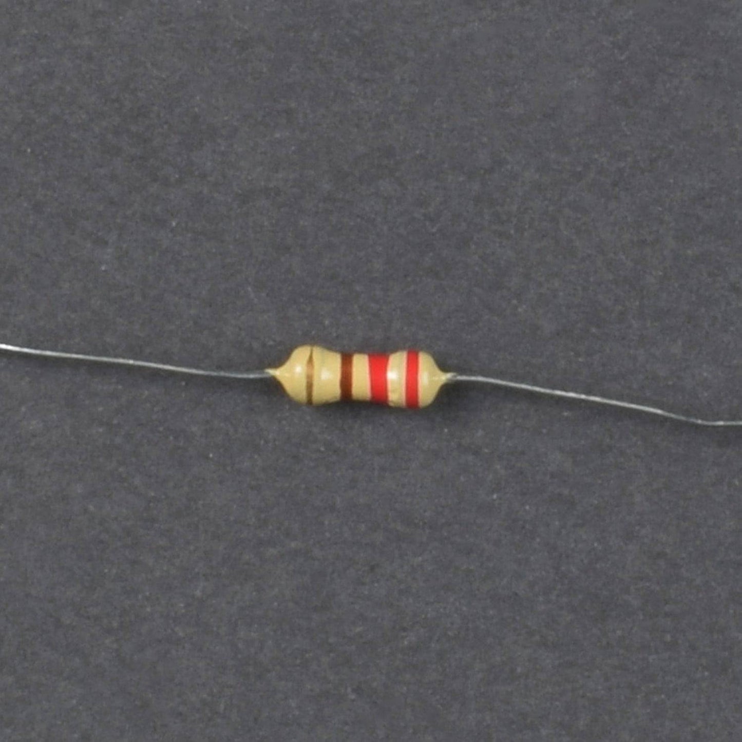
- Resistor 10K - 4, 47K - 2, 680ohm - 4
- Capacitor 10uF - 2, 0.01uF(103) - 2
- Diode 1N4007 - 3
- Push Button - 2
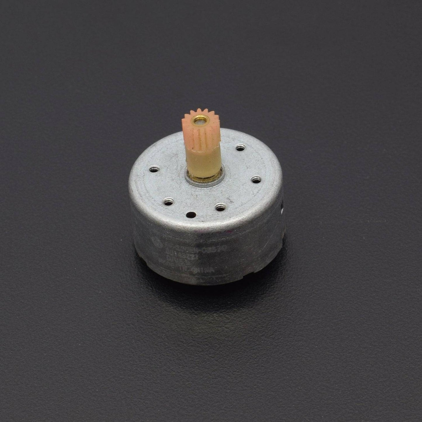
- DC Motor - 1
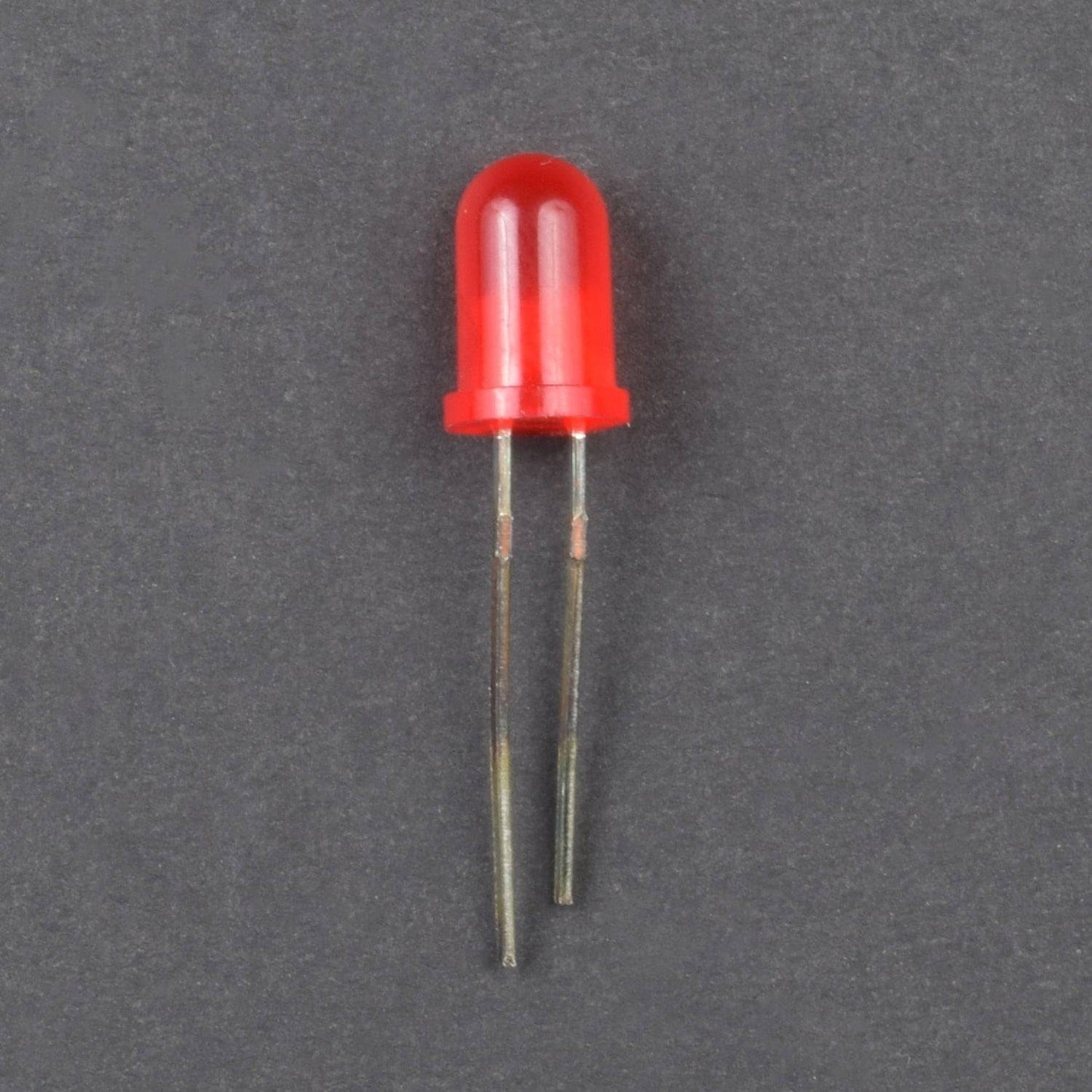
- LED - 5
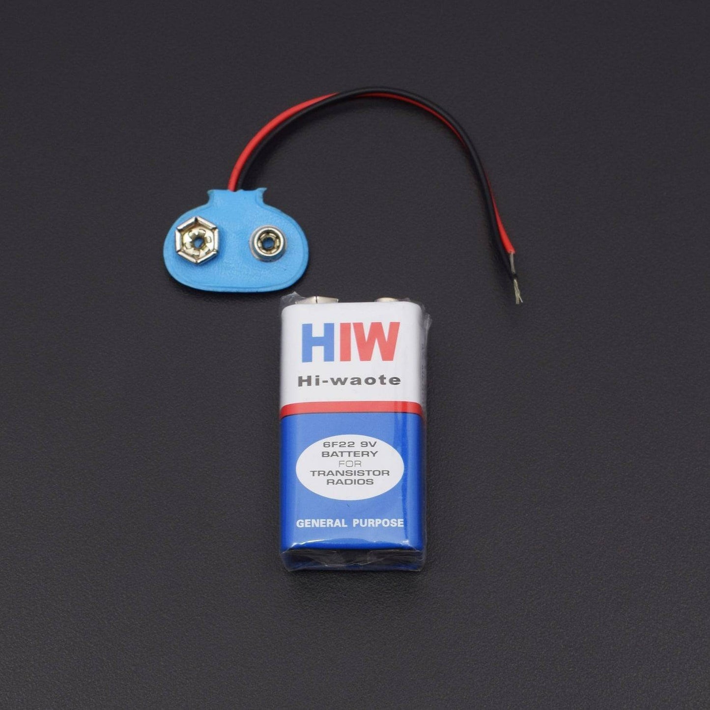
- 9V Battery with battery snapper - 1
- Breadboard 840 points - 1
- Single stand wire 2m - 1
HARDWARE REQUIRED
- 555 Timer IC - 3
- 4017 IC - 1
- Resistor 10K - 4, 47K - 2, 680ohm - 4
- Capacitor 10uF - 2, 0.01uF(103) - 2
- Diode 1N4007 - 3
- Push Button - 2
- DC Motor - 1
- LED - 5
- 9V Battery with battery snapper - 1
- Breadboard 840 points - 1
- Single stand wire 2m - 1
SPECIFICATIONS
power Supply - 5 to 15v
PIN DESCRIPTION
IC 4017

importance Pins look at table below.

1.) Pin 16 is positive power supply and pin 8 is a ground.
The power supply range of 3 volts to 16 volts and Maximum power supply voltage at pin 1 must not much than 18 volts.
2.) When “1” logic, the clock input is stop, and the counter does nothing even when clock pulse arrive.2.)Pin 13 is Clock enabled pins to controls the clock.
When it is “0” logic, the clock is enabled and the counter advances one count for each clock pulse.
3.) Pin 14 is the clock triggers one count.
The clock pulse must be “clean”.
If they are “noisy” the counter may advance two or more times during each clock pulse.
4.) Pin 15 is the reset pin. Normally, it is “0”.
When made “1”, the counter is reset to “0”.
5.) Pins 1-7 and 9-11 are the decoded output pins.
The active count pin goes high and all others remain low.
6.) Pin 12 is Carry output, for the clock input of an additional counter or an external circuit that the count is complete.
Capacitor

Led

555 Timer IC


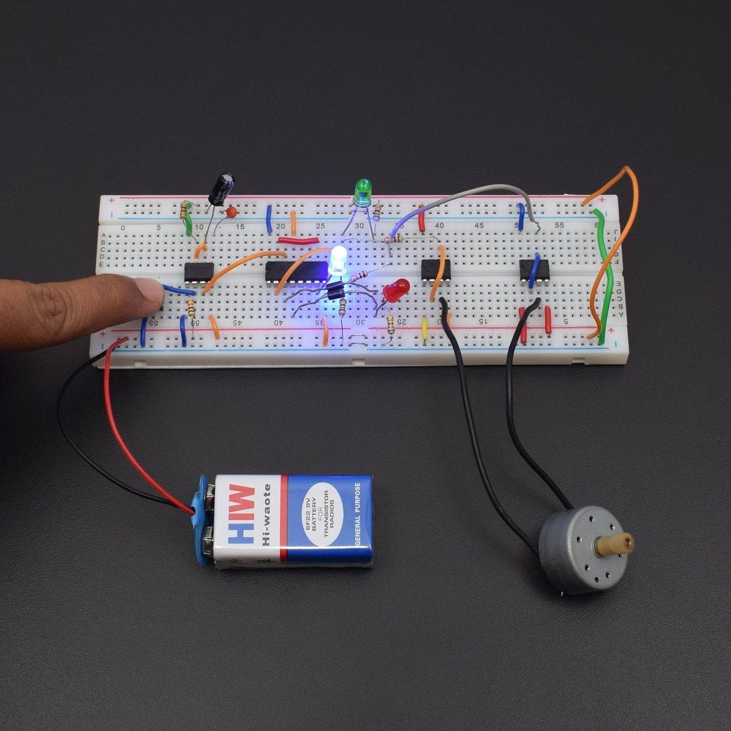
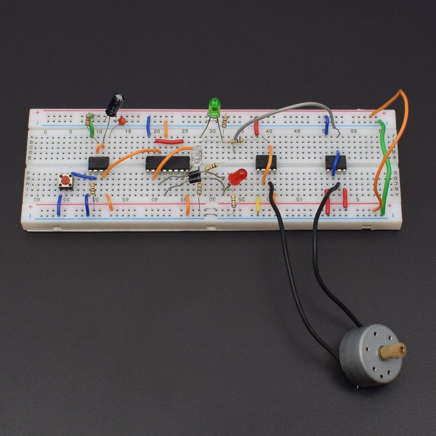
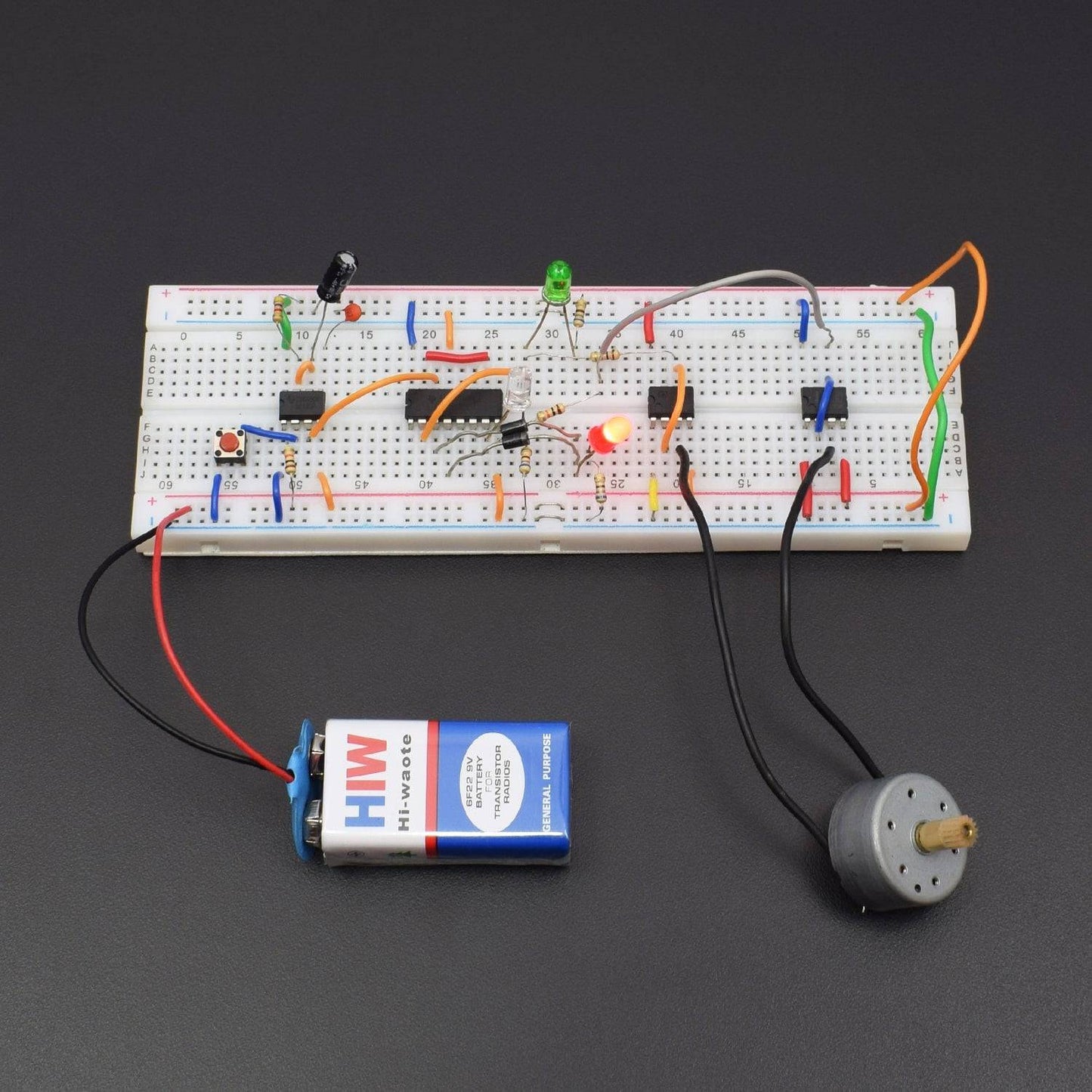
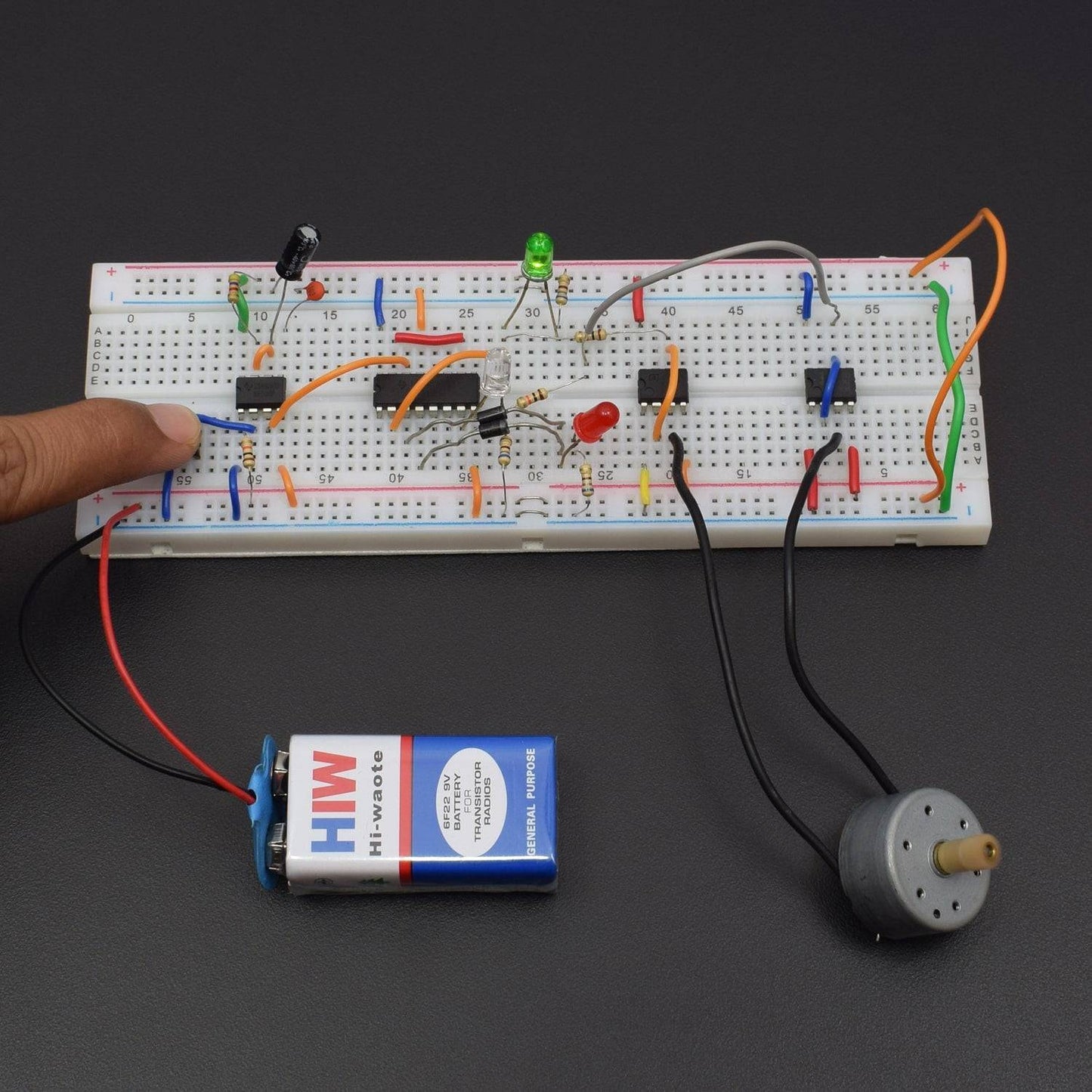
CIRCUIT DESCRIPTION

- All IC's are connected to the breadboard.
- 1st 555 Timer IC pin 1 is GND and Pin 4 & 8 connected to the positive supply.
- 1st 555 IC Pin 2 connected to the 1st leg of push Button and Push Button 2nd leg is GND.
- 1st 555 IC Pin 2 to connected 10K Resistor and Resistor 2nd leg connected to the positive supply.
- 1st 555 IC Pin 6 & 7 connected to the each other and pin 6 to connected 10uF capacitor positive leg and capacitor negative leg is GND.
- 1st 555 IC Pin no. 7 to connected 47K Resistor and Resistor 2nd leg connected to the positive supply, 1st 555 IC Pin 5 to connected 0.01uF(103) capacitor and capacitor 2nd leg is GND.
- Pin 14 of 4017 IC connected to the Pin 3 of 1st 555 IC.
- 4017 IC Pin 8 & 13 are GND and 4017 IC Pin 16 connected to the positive supply.
- 4017 IC Pin 10 & 15 are connected to the each other.
- 4017 IC Pin 3 & 4 to connected 1N4007 diode positive leg and diode negative leg to connected LED(RED) positive leg and led negative leg to connected 680 ohm Resistor and resistor 2nd leg is GND.
- 4017 IC Pin 2 connected to the LED(GREEN) positive leg and led negative leg to connected 680 ohm Resistor and resistor 2nd leg is GND.
- 4017 IC Pin 7 connected to the LED(WHITE) positive leg and led negative leg to connected 680 ohm Resistor and resistor 2nd leg is GND.
- 4017 IC Pin 2 connected to the 10K Resistor and resistor 2nd leg connected to the Pin 6 of 2nd 555 IC.
- 2nd 555 IC Pin 2 & 6 are connected to the each other and Pin 4 & 8 connected to the positive supply and Pin 1 is GND.
- 4017 IC Pin 7 connected to the 10K resistor and Resistor 2nd leg connected to the Pin 6 of 3rd 555 IC.
- 3rd 555 IC Pin 2 & 6 connected to the each other and Pin 4 & 8 connected to the positive supply and Pin 1 is GND.
- 17 DC Motor connected to the Pin 3 of 2nd 555 IC and 3rd 555 IC.
- Breadboard connection positive to positive and negative to negative.

WORKING
You can run a DC motor in clock wise or anti clock wise direction and stop it using a single switch. DC motor control circuit has also another advantage i.e. for proper operation of the motor this circuit provideconstant voltage. Here we use three LEDs LED1 through LED3 for indicates that the motor is in stop, forward rotation and reverse rotation respectively.
The circuit of DC motor control circuit published here utilize three timer IC (IC1, IC3 and IC4) and a decade counter IC2 (CD4017). When we press switch SW1 a false trigger is given to pin 2 of IC1 and output is available. To avoid this false triggering IC1 is used here as monostable multivibrator (timer circuit) for approximately 500 millisecond (ms).
Initially, the circuit DC motor controller is in reset condition with output at pin 3 of IC2 being high. Since output at pin 2 and 7 of IC2 is low, the output of IC3 and IC4 are high and motor does not rotate. This condition or stop condition of motor is indicated by glowing LED1.
When we again press the switch SW1, IC1 provide a clock pulse at pin 14 of IC2 which further advances its output by one and its high state shifts from pin 3 to pin 2. When pin 2 goes high, the output at pin 3 of IC3 goes low due to high trigger. The high output at pin 3 of IC4 rotatemotor in clockwise direction. This state or forward state of motor is indicated by glowing LED2.
Now one another press on switch SW1 shift high output of pin 2 to pin 4 of IC2, which led motor to stop and is indicated by glowing LED1.
Pressing switch SW1 once again shifts the high output of IC2 from pin 4 to 7. The high output at pin 7 of IC2 make low output at pin 3 of IC4 which led motor to rotate in anti-clockwise (reverse) direction. This condition or reverse running of motor is indicated by glowing LED3.
If SW1 is pressed again, the high output is sifted from pin 7 to pin 10. Since pin 10 is connected to reset pin 15 of IC2, it reset decade counter CD4017 and made pin 3 high. So the motor does not rotate. LED1 glows via diode D1 to indicate that the motor is in stop condition.