


vendor-unknown
Control two Servo Motors using Joystick Module interfacing with Arduino Uno - KT842
Control two Servo Motors using Joystick Module interfacing with Arduino Uno - KT842
SKU:KT842
1000 in stock
Couldn't load pickup availability
- For Bulk Order Click Here
- Need Customer Support?
- Free Delivery Above 999/-
Note: In case you receive a damaged or faulty product, please return it in the original box with all foam and packaging. Returns will not be accepted if further damage occurs due to improper packing.
If you order a product that is currently in Preorder, and the price of that item increases in the future, you will be required to pay the difference in price.
For refund/return/replacement, call us at +91 95995 94520 or email us at support@rees52.com
Delivery Time
Delivery Time
- Delivery time with the Express Shipping option is 2-3 working days, and with the Standard Shipping option is 5-6 working days. It varies based on location, reliant on courier services.
- Delivery time if the order item is on Preorder Status is 15-20 working days.
COD (Cash on Delivery)
COD (Cash on Delivery)
- For COD you have to pay extra charges of Rs 350/- before the shipment. (We will share the company QR Code, UPI ID or Account details for the same)
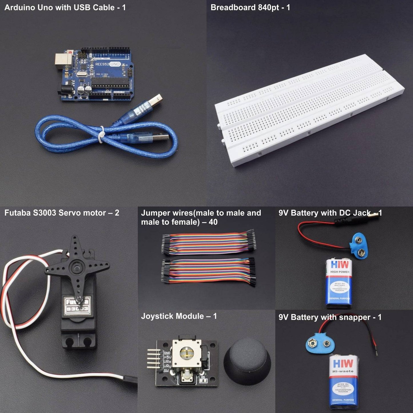
Hardware required
- Arduino Uno with USB Cable – 1
- 840 points breadboard – 1
- Jumper wires male to female – 40 pcs
- Jumper wires male to male – 40 pcs
- Futaba S3003 Servo motor – 2
- Joystick Module – 1
- 9v Battery -2
- DC Jack – 1
- snapper - 1
HARDWARE REQUIRED
- Arduino Uno with USB Cable – 1
- 840 points breadboard – 1
- Jumper wires male to female – 40 pcs
- Jumper wires male to male – 40 pcs
- Futaba S3003 Servo motor – 2
- Joystick Module – 1
- 9v Battery -2
- DC Jack – 1
- snapper - 1
SOFTWARE REQUIRED
Arduino IDE 1.8.5 (programmable platform for Arduino)
Click To Download :https://www.arduino.cc/en/Main/Software

SPECIFICATIONS
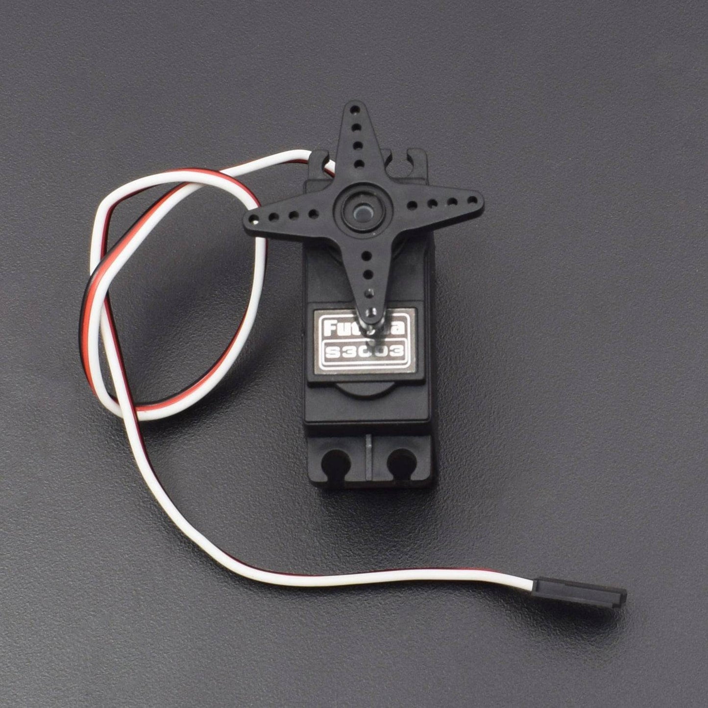
FUTABA S3003 SERVO MOTOR
- Operating Voltage: 4.8-6.0 Volts
- Operational current: 100mA
- Operating Speed (4.8V): 0.23sec/60 degrees at no load
- Operating Speed (6.0V): 0.19sec/60 degrees at no load
- Stall Torque (4.8V): 44 Oz/in. (3.2kg.cm)
- Stall Torque (6.0V): 56.8 Oz/in. (4.1kg.cm)
- Motor Type: 3 Pole Ferrite
- Operating Angle: 45 Deg. one side pulse traveling 400µsec
JOYSTICK MODULE
A joystick is an input device consisting of a stick that pivots on a base and reports its angle or direction to the device it is controlling. The Joystick Module is a tiny low cost option to add a game like control to your projects. Be it robotics or any other project that requires a precise human control. The module has two potentiometers for the X and Y axis measurements. Also a switch that can give an additional control option.
- Supply Voltage: 3.3V to 5V
- Interface: Analog x2,Digital x1
- PH2.0 Interface
- Size:35x39mm
- Weight:15g
- 3 axes: X, Y (potentiometers) and Z (button)
- Potentiometers (X and Y): 2 x 5Kohm
- Button: normally open (Z)
- Strip Connection: 2.54mm
PIN DESCRIPTION
JOYSTICK MODULE
3 axes: X, Y (potentiometers) and Z (button)

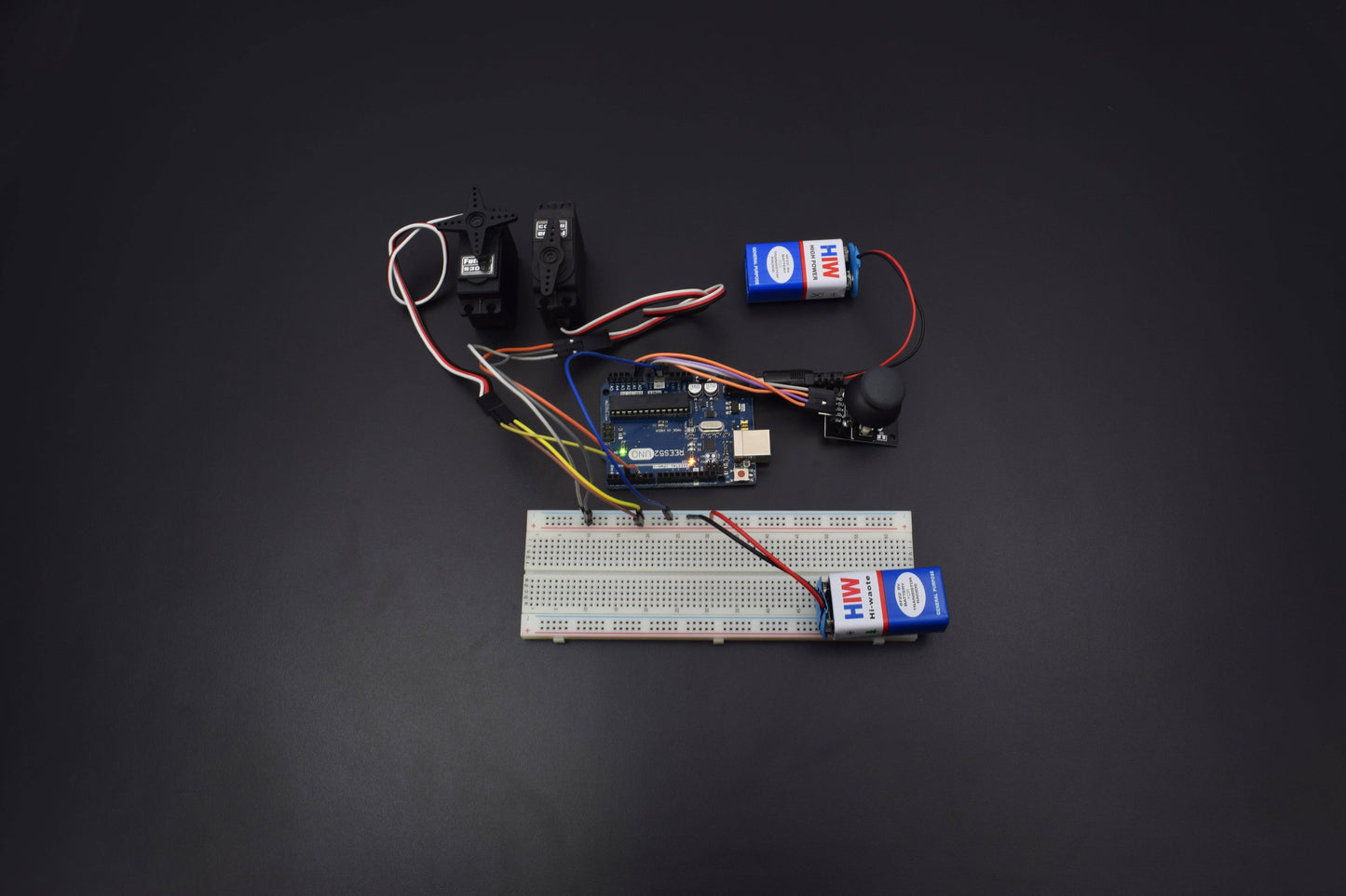
CIRCUIT DESCRIPTION
- The external battery VCC / GND connect to the breadboard.
- The Arduino GND connect to the breadboard's GND input
The servo connections we use in this project are as follows;
- Orange Input - Signal Input
- Red Input - Power Input (VCC)
- Brown Input - Ground Input(GND)
- The Servo1 VCC and GND connect to the breadboard's VCC / GND inputs
- The Servo1 Signal connect to the Arduino Digital PWM 3
- The Servo2 VCC and GND connect to the breadboard's VCC / GND inputs
- The Servo2 Signal connect to the Arduino Digital PWM 5
The joystick connections we use in this project are as follows;
- The Joystick GND connect to the Arduino GND
- The Joystick VCC connect to the Arduino VCC
- The Joystick 'X' (in some modules 'H') connects to the Arduino Analog 0
- The Joystick 'Y' (in some modules 'V') connects to the Arduino Analog 1
The Joystick 'SW' (switch or button) not connected
CODE
CLICK TO SEE THE CODE:
WORKING
- In this set up we are controlling two servo motors with the help of a joystick module.
- When we move the joystick module stick in different direction we see the rotation of the servo motors