


Generic
Control the LEDs using Hall Magnetic Sensor Module compatible with Arduino Uno - KT621
Control the LEDs using Hall Magnetic Sensor Module compatible with Arduino Uno - KT621
SKU:KT621
50 in stock
Couldn't load pickup availability
- For Bulk Order Click Here
- Need Customer Support?
- Free Delivery Above 999/-
Note: In case you receive a damaged or faulty product, please return it in the original box with all foam and packaging. Returns will not be accepted if further damage occurs due to improper packing.
If you order a product that is currently in Preorder, and the price of that item increases in the future, you will be required to pay the difference in price.
For refund/return/replacement, call us at +91 95995 94520 or email us at support@rees52.com
Delivery Time
Delivery Time
- Delivery time with the Express Shipping option is 2-3 working days, and with the Standard Shipping option is 5-6 working days. It varies based on location, reliant on courier services.
- Delivery time if the order item is on Preorder Status is 15-20 working days.
COD (Cash on Delivery)
COD (Cash on Delivery)
- For COD you have to pay extra charges of Rs 350/- before the shipment. (We will share the company QR Code, UPI ID or Account details for the same)


INTRODUCTION
In this project, we will learn about the basic functionality of a Hall Magnetic Sensor by controlling the LEDs using a Magnet.
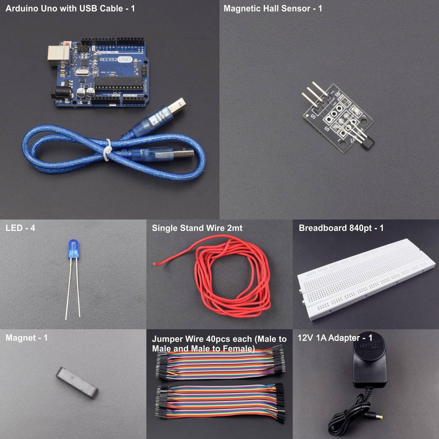
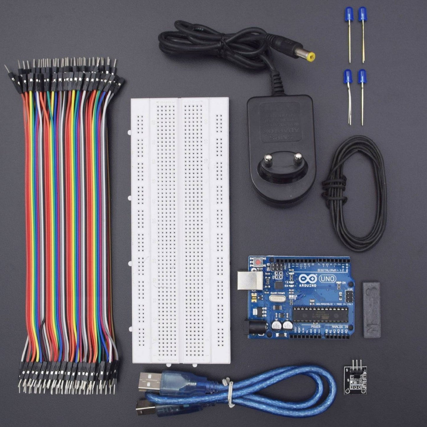
HARDWARE REQUIRED
- Arduino Uno With USB Cable - 1
- Magnetic Hall Sensor Module - 1
- 12V 2A Adapter - 1
- Led - 4
- Single Stand Wire - 1
- Bread Board 840 Point - 1
- Jumper Wire (male to male) - 40 pcs
- Jumper Wire (male to female) - 40 pcs
SOFTWARE REQUIRED
Arduino IDE 1.8.5 (programmable platform for Arduino)
Click To Download: https://www.arduino.cc/en/Main/Software
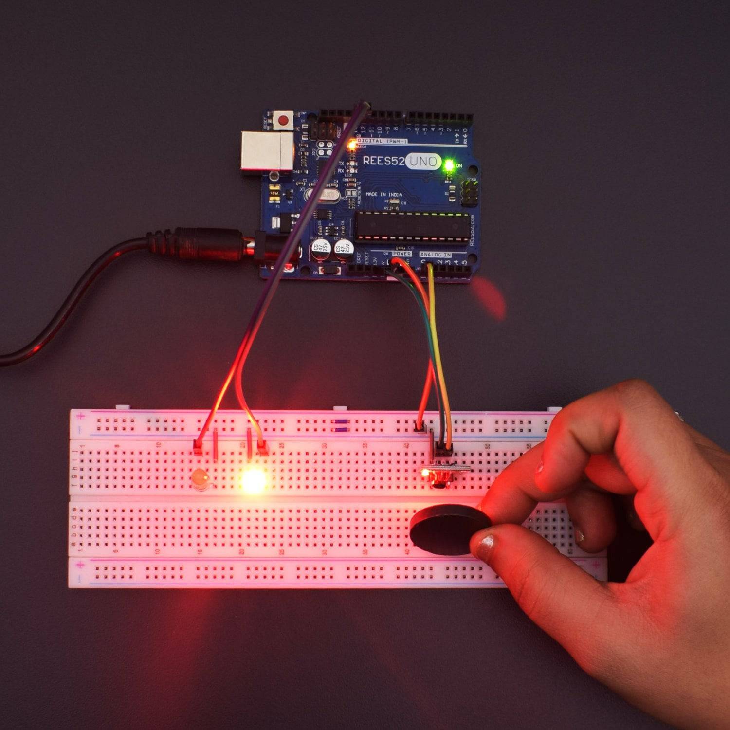
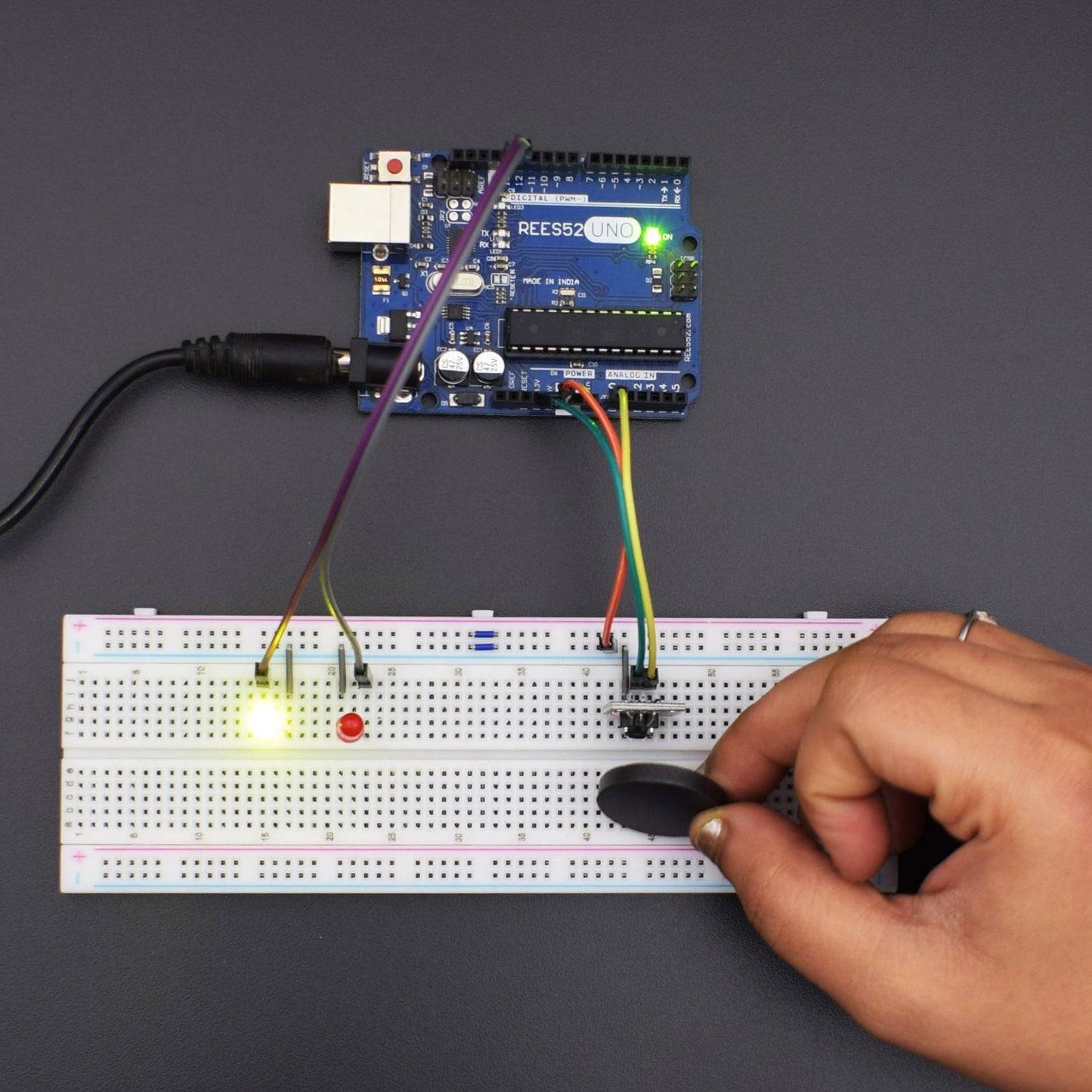
CIRCUIT CONNECTION
- Attach two LEDs on the Breadboard.
- Connect GND of Arduino Uno with Breadboard for further GND connections.
- Connect the positive terminal of LED 1 with Digital Pin 12 of Arduino
- Connect the positive terminal of LED 2 with Digital Pin 13 of Arduino
- Connect the GND of both LEDs with the GND rail of the Breadboard.
- Connect the GND of the Hall Magnetic Sensor with the GND of the Arduino Uno.
- Connect VCC of Hall Magnetic Sensor with Pin 3.3V of Arduino Uno.
- Connect the Pin Signal of the Hall Magnetic Sensor with the Analog Pin A0 of Arduino Uno.
CODE
https://drive.google.com/open?id=1zM3t2JHUmBc5DrAggk4hv9-MjbKu2ofK
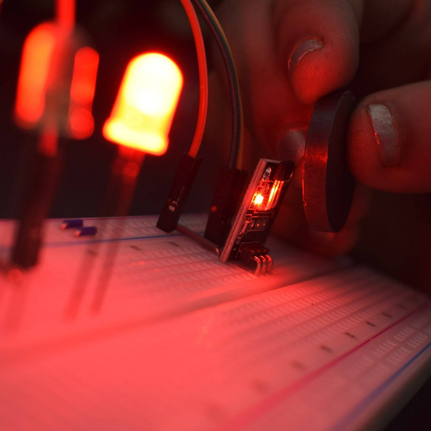
WORKING
Welcome to the Arduino-Based Project which consists of a Hall Magnetic Sensor. Magnetic sensors are solid-state devices that can be used in many different types of applications such as sensing position, velocity or directional movement. Hall Effect Sensors are devices which are activated by an external magnetic field. The magnetic field has two important characteristics flux density, (B) and polarity (North and South Poles). The output signal from a Hall Effect sensor is the function of magnetic field density around the device. When the magnetic flux density around the sensor exceeds a certain pre-set threshold, the sensor detects it and generates an output voltage called the Hall Voltage, VH. Here, we will see the Northern and Southern poles of the Magnet as we place it on either side towards the Sensor.