


REES52
Control the intensity of led using LDR interfacing with Arduino Uno - KT590
Control the intensity of led using LDR interfacing with Arduino Uno - KT590
SKU:KT590
160 in stock
Couldn't load pickup availability
- For Bulk Order Click Here
- Need Customer Support?
- Free Delivery Above 999/-
Note: In case you receive a damaged or faulty product, please return it in the original box with all foam and packaging. Returns will not be accepted if further damage occurs due to improper packing.
If you order a product that is currently in Preorder, and the price of that item increases in the future, you will be required to pay the difference in price.
For refund/return/replacement, call us at +91 95995 94520 or email us at support@rees52.com
Delivery Time
Delivery Time
- Delivery time with the Express Shipping option is 2-3 working days, and with the Standard Shipping option is 5-6 working days. It varies based on location, reliant on courier services.
- Delivery time if the order item is on Preorder Status is 15-20 working days.
COD (Cash on Delivery)
COD (Cash on Delivery)
- For COD you have to pay extra charges of Rs 350/- before the shipment. (We will share the company QR Code, UPI ID or Account details for the same)
INTRODUCTION
In this project, we will work on a Photoresistor (Photovaristor) which includes the photoelectric effect of the semiconductor. Photovaristor is commonly applied in the measurement of light and light control.
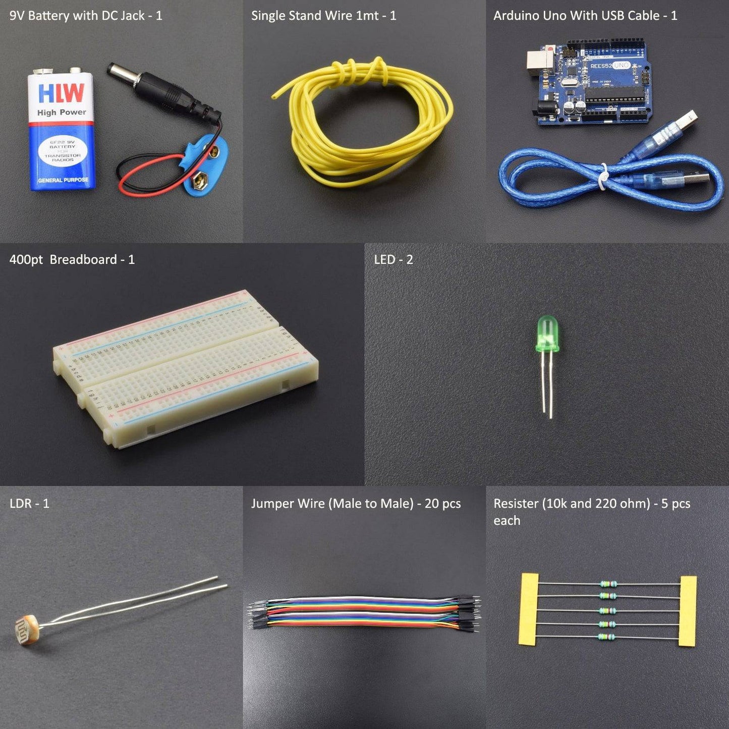
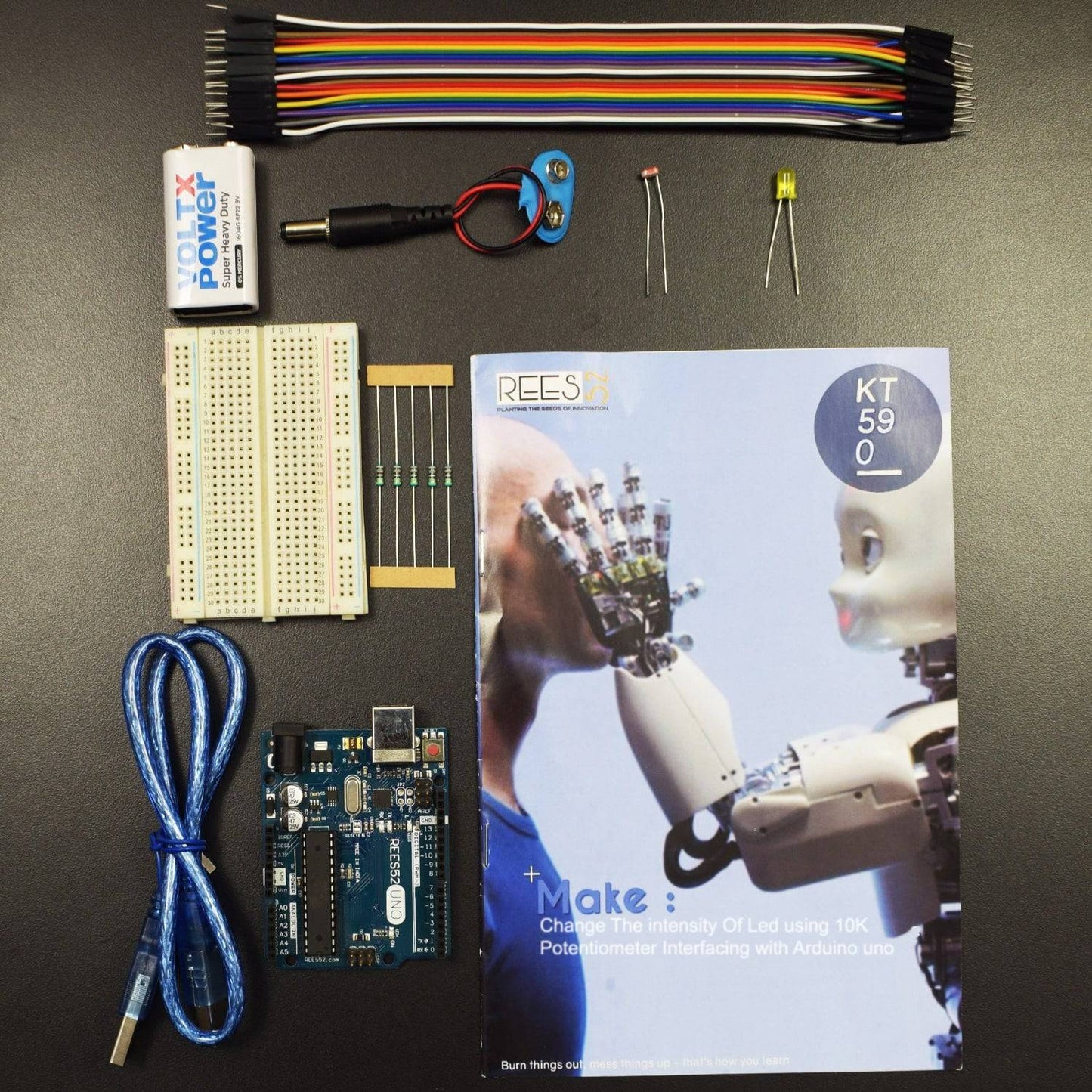
HARDWARE REQUIRED
- Arduino UNO with USB cable - 1
- Male to Male jumper wires – 20 pieces
- 9v Battery - 1
- Snapper with DC Jack – 1
- 400 pt. Breadboard - 1
- LDR Photoresistor -2
- 10KΩ Resistor – 5
- 220Ω Resistor – 5
- Led - 2
NOTE: A 9V Battery is used as an external power supply.
SOFTWARE REQUIRED
Arduino IDE 1.8.5 (programmable platform for Arduino)
Click To Download: https://www.arduino.cc/en/Main/Software
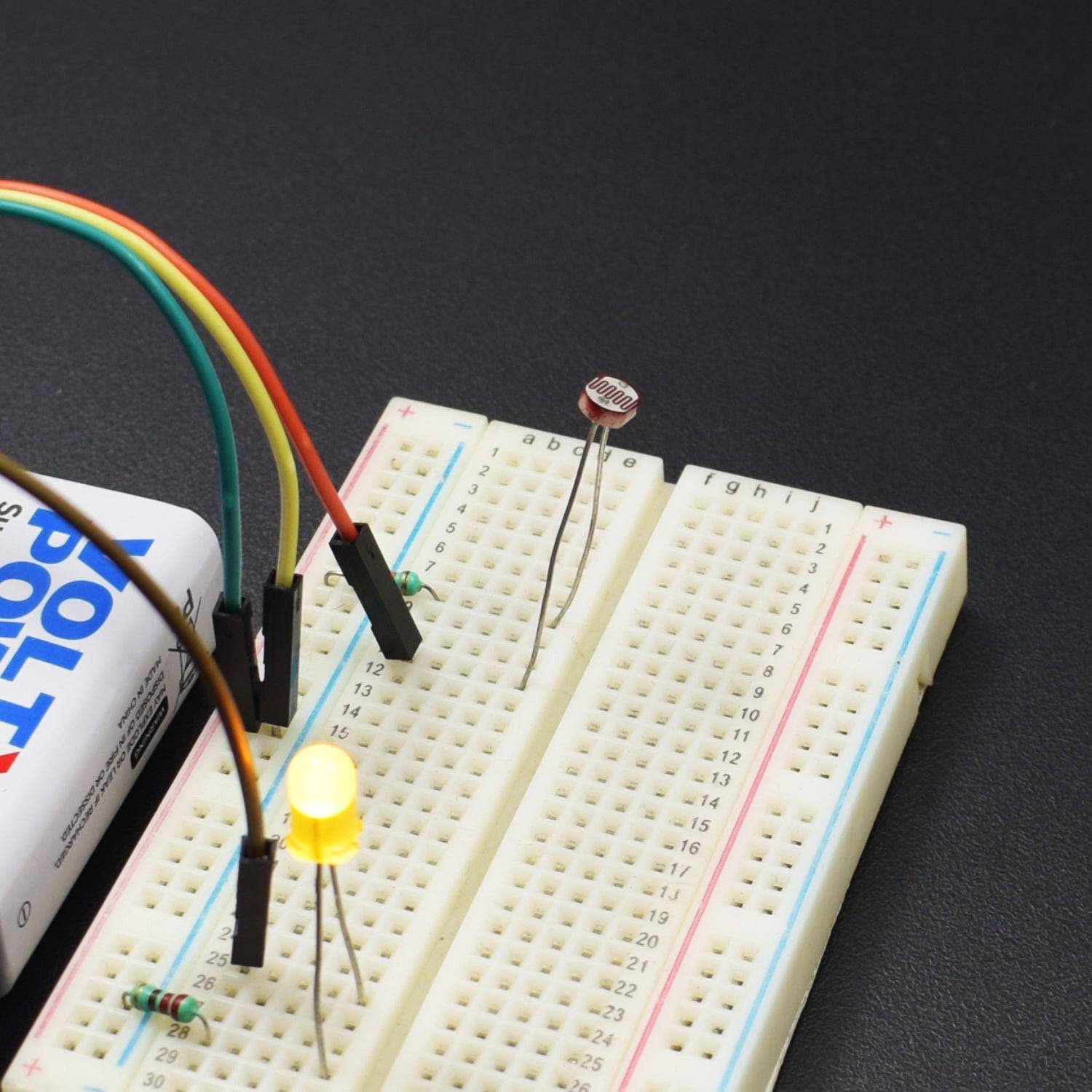
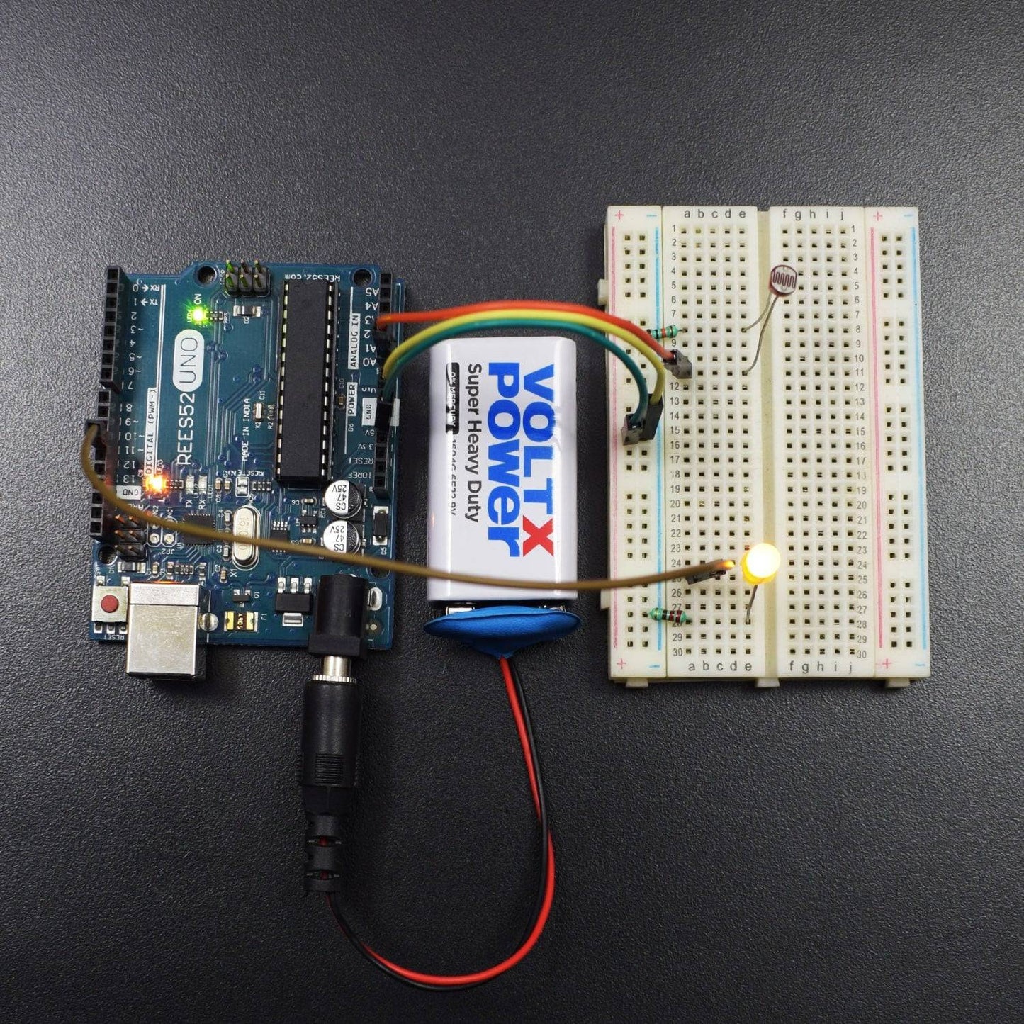
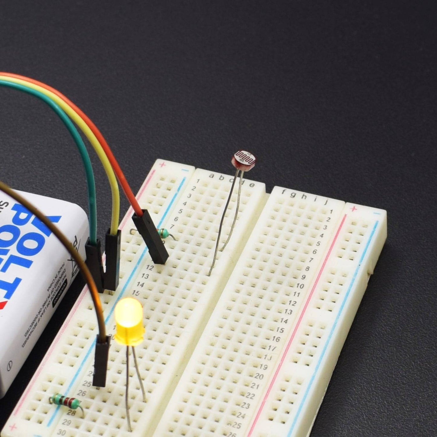
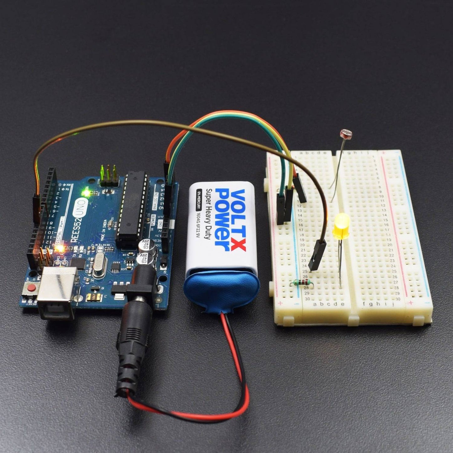
CIRCUIT CONNECTION
- Attach LED and LDR on the Breadboard.
- Connect GND of Arduino Uno with Breadboard to make further GND connections.
- Connect 5V Pin of Arduino Uno with the Breadboard for further 5V power supply connections.
- Connect the positive terminal of LED with the Digital Pin 11 of the Arduino Uno.
- Connect the negative terminal of the LED with the GND rail of the Breadboard via the 220Ω resistor.
- Connect one leg of LDR with the 5V power supply rail of the Breadboard via a 10KΩ resistor on one end and connect another end with the Analog Pin A0 of Arduino Uno.
- Connect another leg of the LDR with the GND rail of the Breadboard.
CODE
WORKING AND OUTPUT
Welcome to the Arduino-based project in which we have used the analogWrite (PWM interface, analogue value) function. In this project, we will read the analog value of the potentiometer and assign the value to the PWM port, so there will be a corresponding change to the brightness of the LED. One final part will be displaying the analogue value on the screen. You can consider this as the "analog value reading" project adding the PWM analog value assigning part. After downloading the program, when we rotate the potentiometer knob, we can see changes in the displaying value, also an obvious change in the LED brightness on the breadboard.