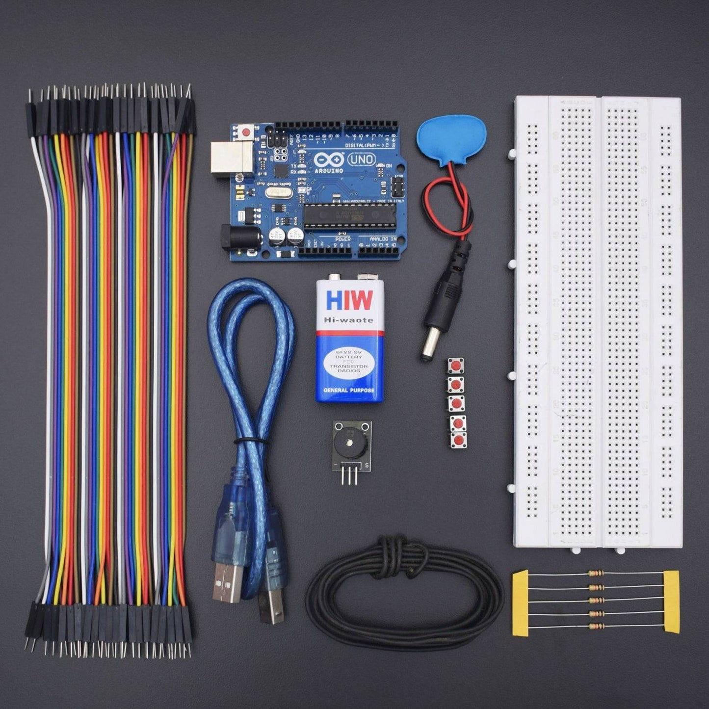
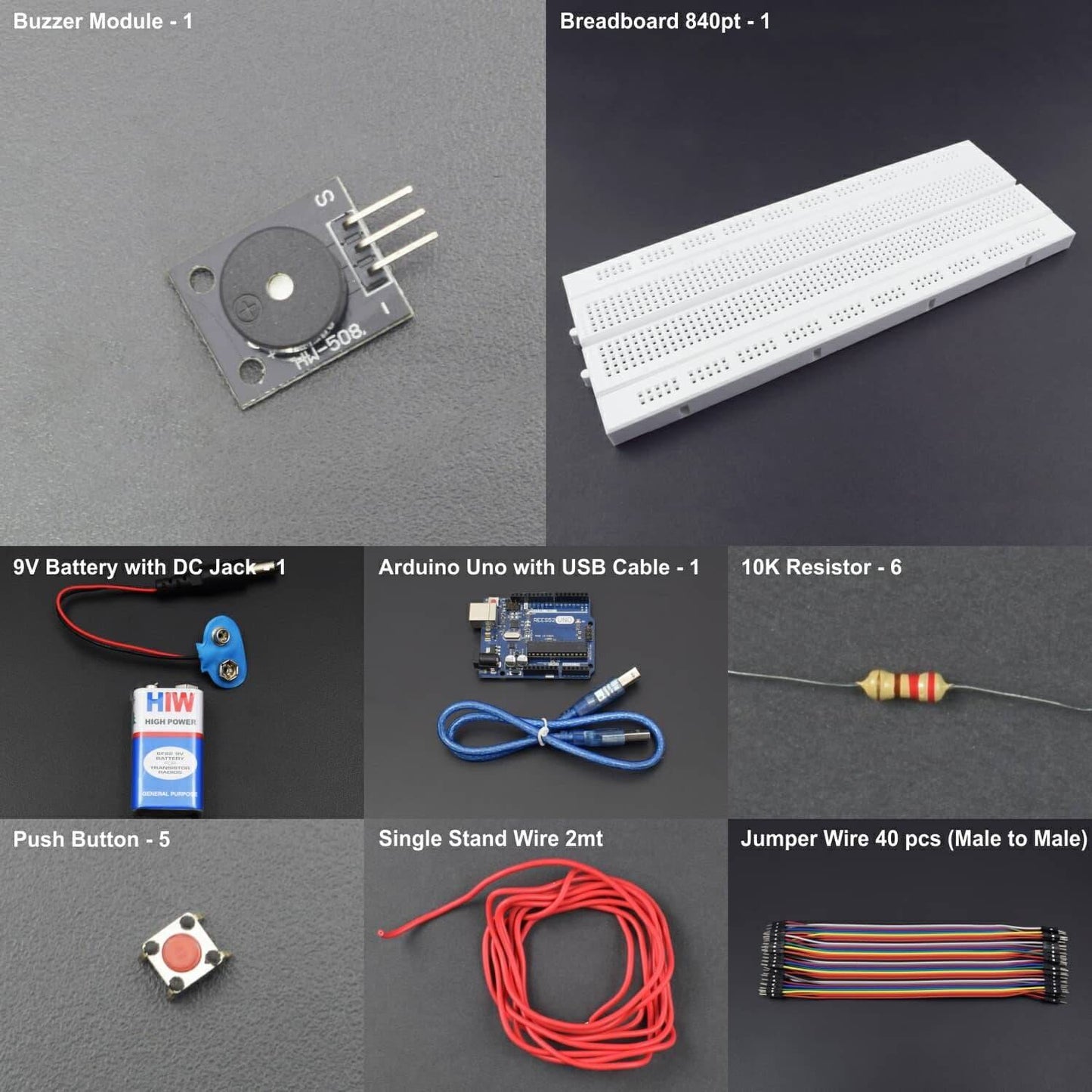

Hardware Required
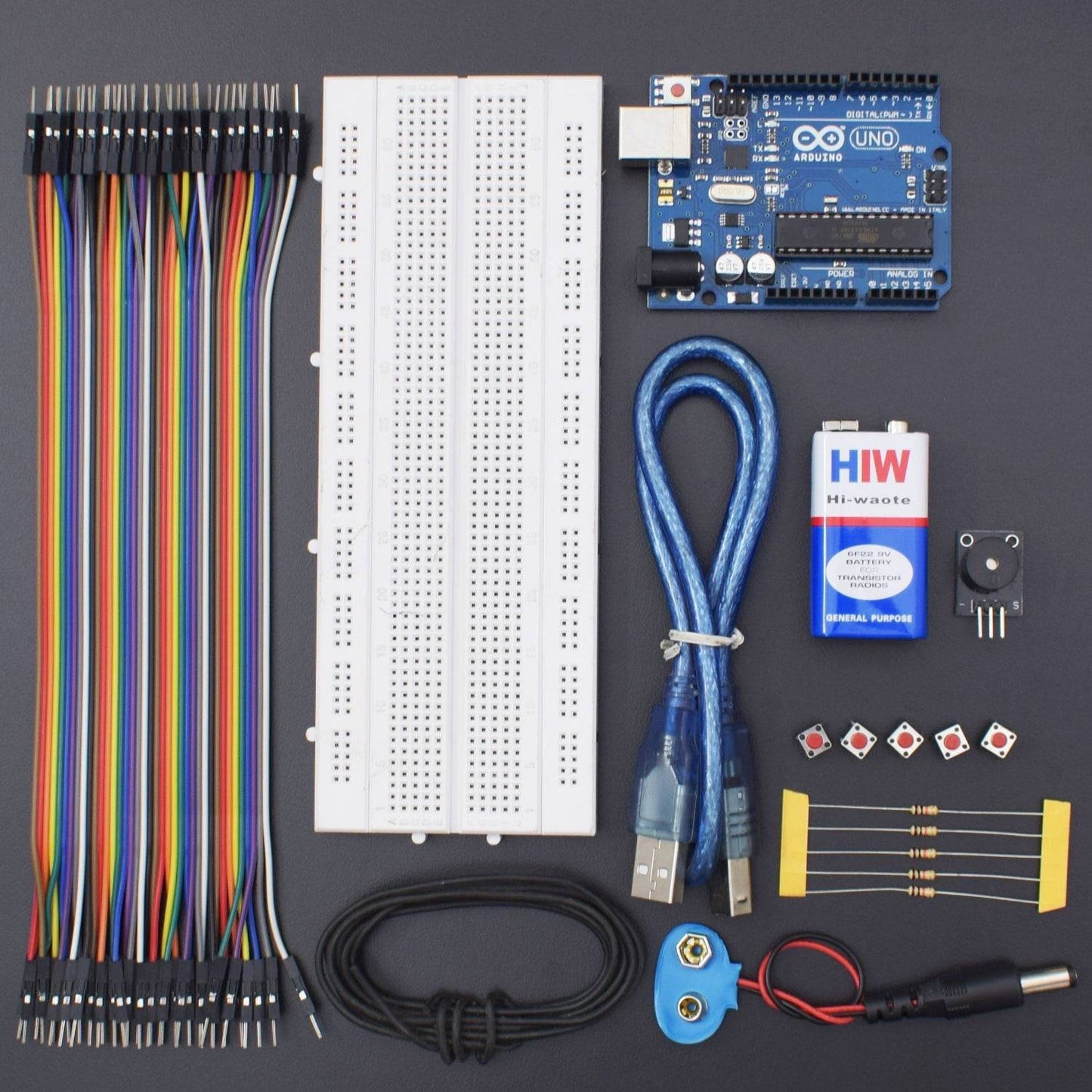
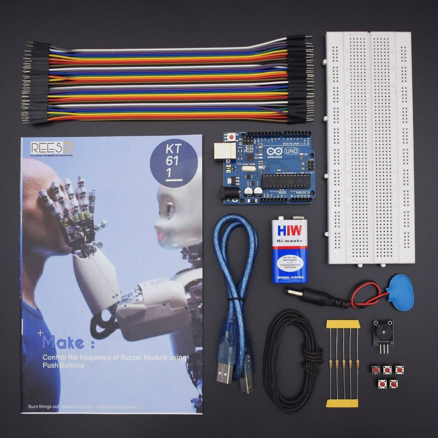
- Arduino Uno With USB Cable - 1
- Buzzer Module - 1
- 9v Battery - 1
- Snapper With DC Jack - 1
- Bread Board 840 Point - 1
- Jumper Wire (male to male) - 40 pcs
- Single Stand Wire - 1
- Push Button - 5
- 10k ohm Resistance - 6
Introduction
In this project, we have used buzzer module which will be controlled by the series of Buttons and generate various tones.
HARDWARE REQUIRED
- Arduino Uno With USB Cable - 1
- Buzzer Module - 1
- 9v Battery - 1
- Snapper With DC Jack - 1
- Bread Board 840 Point - 1
- Jumper Wire (male to male) - 40 pcs
- Single Stand Wire - 1
- Push Button - 5
- 10k ohm Resistance - 6
SOFTWARE REQUIRED
Arduino IDE 1.8.5 (programmable platform for Arduino)
Click To Download:https://www.arduino.cc/en/Main/Software
SPECIFICATIONS
Buzzer Module
Active Buzzer Module produces a single-tone sound when signal is high. To produce different tones use the Passive Buzzer Module. It consists of an active piezoelectric buzzer, it generates a sound of approximately 2.5 kHz when signal is high.
Operating Voltage |
3.5V ~ 5.5V |
Maximum Current |
30mA / 5VDC |
Resonance Frequency |
2500Hz ± 300Hz |
Minimum Sound Output |
85Db @ 10cm |
Working Temperature |
-20°C ~ 70°C [-4°F ~ 158°F] |
Storage Temperature |
-30°C ~ 105°C [-22°F ~ 221°F] |
Dimensions |
18.5mm x 15mm [0.728in x 0.591in] |
Arduino Uno

CIRCUIT CONNECTION
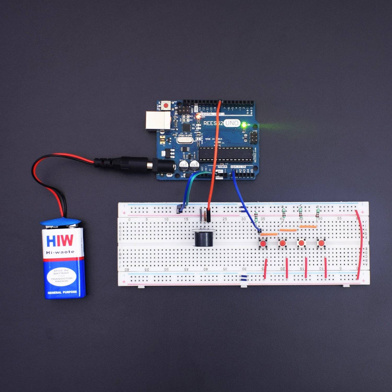
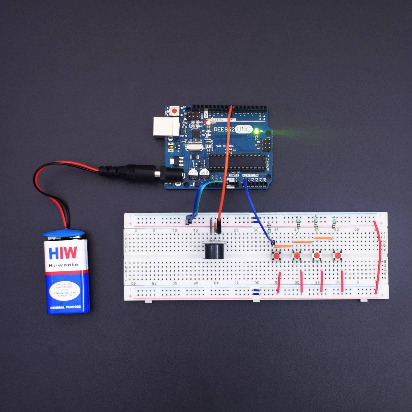
- Attach four buttons on Breadboard.
- Connect GND of Arduino Uno with Breadboard for further GND connections.
- Connect Pin 5V of Arduino Uno with Breadboard for further 5V power supply connections.
- Connect one terminal of Button 1 with Analog Pin A0 of Arduino Uno via 10K Ohm resistor.
- Connect one terminal of Button 2 with Analog Pin A0 of Arduino Uno via 10K Ohm resistor.
- Connect one terminal of Button 3 with Analog Pin A0 of Arduino Uno via 10K Ohm resistor.
- Connect one terminal of Button 4 with Analog Pin A0 of Arduino Uno via 10K Ohm resistor.
- Connect other end of all resistors with GND rail of Breadboard.
- Connect other terminal of all buttons with 5V rail of Breadboard.
- Connect VCC of Buzzer with 5V rail of Breadboard.
- Connect GND of Buzzer with GND rail of Breadboard.
- Connect Pin Signal of Buzzer with Digital Pin 8 of Arduino Uno.

CODE
https://drive.google.com/open?id=1zWxx9yW6HiaNEgqp_LJXE_Rlx4LJD8TM
WORKING
Welcome to the Arduino Based Project which consists of Passive Buzzer. The basic working principle of Buzzer is being described here. After uploading the code, when you press the button, Buzzer module generates sound due to the internal oscillation. The buzzer module which will change the frequency of tone from High to Low volume after every button pressed.


