
vendor-unknown
Control the directional Rotation of Stepper Motor by pressing push button Interfacing With Arduino uno - KT994
Control the directional Rotation of Stepper Motor by pressing push button Interfacing With Arduino uno - KT994
SKU:KT994
1000 in stock
Couldn't load pickup availability
- For Bulk Order Click Here
- Need Customer Support?
- Free Delivery Above 999/-
Note: In case you receive a damaged or faulty product, please return it in the original box with all foam and packaging. Returns will not be accepted if further damage occurs due to improper packing.
If you order a product that is currently in Preorder, and the price of that item increases in the future, you will be required to pay the difference in price.
For refund/return/replacement, call us at +91 95995 94520 or email us at support@rees52.com
Delivery Time
Delivery Time
- Delivery time with the Express Shipping option is 2-3 working days, and with the Standard Shipping option is 5-6 working days. It varies based on location, reliant on courier services.
- Delivery time if the order item is on Preorder Status is 15-20 working days.
COD (Cash on Delivery)
COD (Cash on Delivery)
- For COD you have to pay extra charges of Rs 350/- before the shipment. (We will share the company QR Code, UPI ID or Account details for the same)


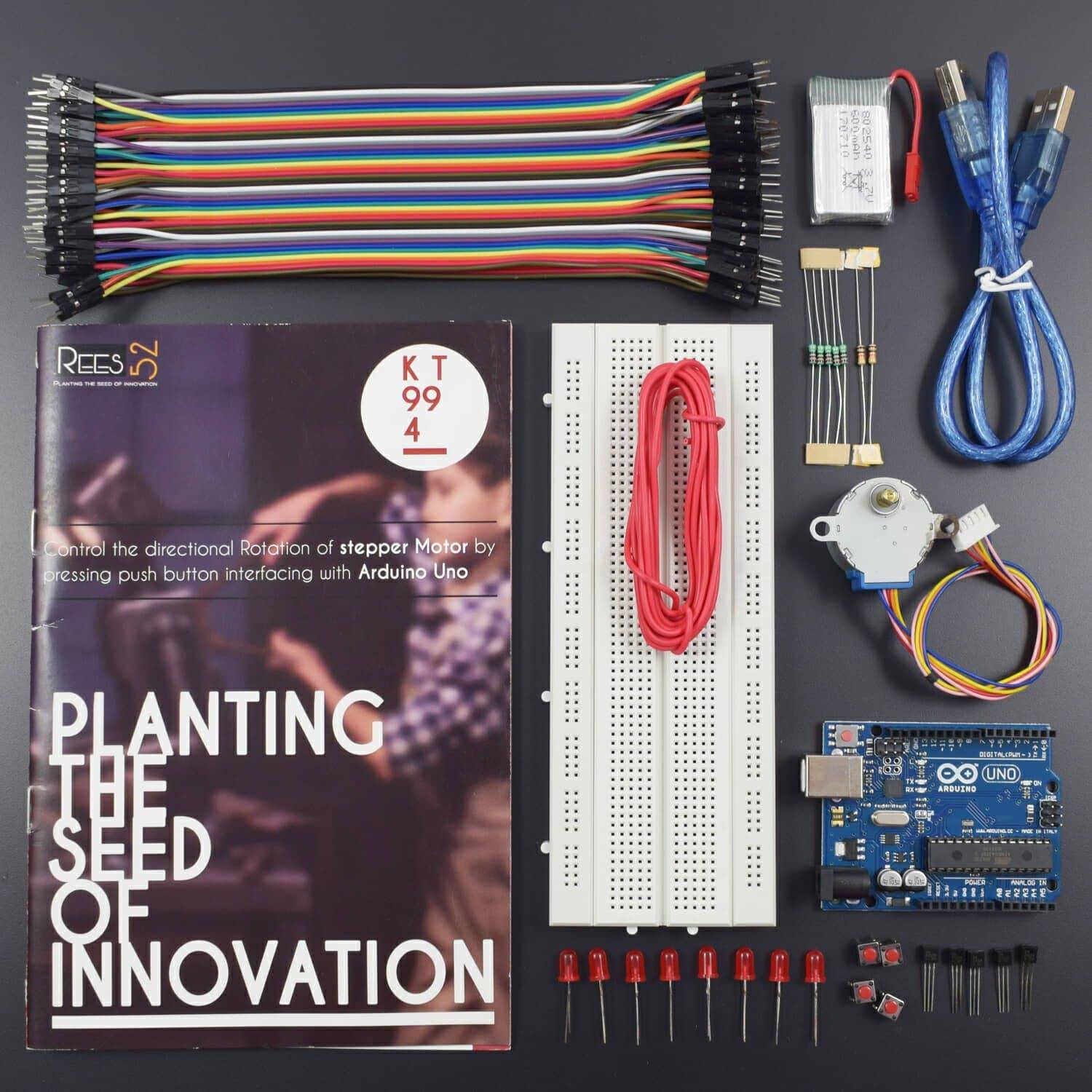
Kit Includes
- Arduino UNO with Usb cable – 1
- Jumper Wires male to male-40 piece
- Jumper Wires male to female -40 piece
- Led – 4
- 28BYJ-48 Stepper Motor – 1
- 600 mah rechargeable battery – 1
- Breadboard 840 points – 1
- Single Stand Wire 2mt-1
- Resistor 10 k – 1
- Resistor 220 ohm – 4
- Transistor 2n2222 npn –4
HARDWARE REQUIRED
- Arduino UNO with Usb cable – 1
- Jumper Wires male to male-40 piece
- Jumper Wires male to female -40 piece
- Led – 4
- 28BYJ-48 Stepper Motor – 1
- 600 mah rechargeable battery – 1
- Breadboard 840 points – 1
- Single Stand Wire 2mt-1
- Resistor 10 k – 1
- Resistor 220 ohm – 4
- Transistor 2n2222 npn –4
SOFTWARE REQUIRED
Arduino IDE 1.8.5 (programmable platform for Arduino)
Click To Download: https://www.arduino.cc/en/Main/Software


TYPICAL APPLICATION
- Digitally controlled as part of an open-loop system for use in holding or positioning applications
- In the field of lasers and optics, they are frequently used in precision positioning equipment such as linear actuators, linear stages, rotation stages, goniometers, and mirror mounts. Other uses are in packaging machinery and positioning of valve pilot stages for fluid control systems.
- Commercially, stepper motors are used in floppy disk drives, flatbed scanners, computer printers, plotters, slot machines, image scanners, compact disc drives, intelligent lighting, camera lenses, CNC machines and, more recently, in 3D printers
SPECIFICATIONS
Stepper motor
Operating voltage – up to 15 v
This Motor has a Gear ratio of 64, and Stride Angle 5.625° so this motor has a 4096 Steps.
Steps = Number of steps in One Revolution * Gear ratio.
Steps= (360°/5.625°)*64"Gear ratio" = 64 * 64 =4096. This value will substitute it on the arduino Sketch

PIN DESCRIPTION
Stepper motor

2N2222 Transistor
From the flat surface


Led

CIRCUIT DIAGRAM


The circuit is sectioned into 2 parts
- The Button Section
- The Stepper driver section
Step 1: Button Section
Connect the 2 negative rails of the breadboard to the ground pin of the Arduino,
Then connect the 2 positive rails of the breadboard to the 5v pin of the Arduino.
Let's start off with the button section.
Place the button on the breadboard (In the final slider there are 2 contact points that will be closed once the sliding unit reaches either end).
- Connect one end of the button to the positive rail
- Connect the other end of the button to the ground using the 10K resistor.
- Connect pin 3 of the Arduino to the intersecting point of the button and resistor.
Step 2: Stepper Driver Circuit
Now let's start building the stepper driver circuit
(It's important to note here that the transistors must be able to handle the max current draw of the stepper motor, you can find this info on the datasheets).
Place a transistor on the breadboard
For the pn2222 transistor, the first pin is the Emitter, connect the Emitter pin to the ground rail.
The collector is the 3rd pin on the pn2222, connect a lead to the Collector of the transistor and let it hang (We will be using this to connect the stepper motor later).
The middle pin is the Base, connect an LED to the Base of the Transistor and another terminal strip.
Connect one of the 220 Ohm resistors to the LED and to another terminal strip.
Connect a lead between the resistor and the Arduino.
Repeat this process until you have 4 of these "Electronic switches" connected to pins 5, 6, 7 and 8.
Step 3: Connecting the Stepper Motor


Moving on to the connection of the stepper motor.
- Connect a lead between the positive rail and the positive of the stepper motor.
- Connect the leads hanging in the breeze to the stepper motor.
Ensure to connect the leads using the order found in the datasheet of the stepper motor.
CODE
Click to see the code or copy the link to see the code
https://drive.google.com/open?id=1z1LA2Qs-Q7I0h-s7LLCamEWak3Hxku2a
WORKING
This program runs the stepper motor and decides what to do when the button is pressed.
The program continuously checks to see if the button is pressed.
The motor goes in one direction until the button is pressed down then the motor will reverse its direction and keep on going in that direction even when the button is released.
If the button is pressed again it will reverse its direction again.
In the motor control section of the program.
It follows a sequence of sending a signal to the pins on the Arduino and in turn switches the LEDs and Transistors on and off to make the motor step to that sequence.