Hardware Required
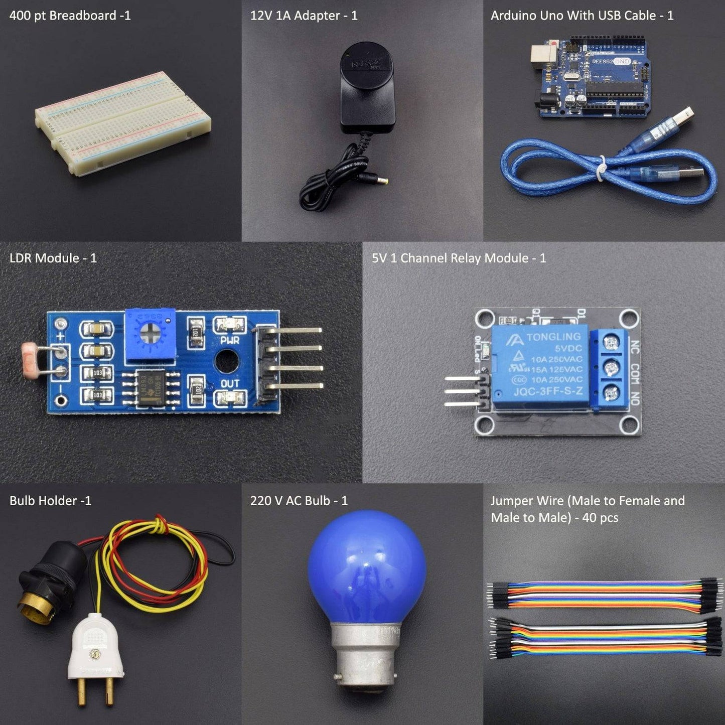
- LDR Module - 1
- 12V 1A Adapter - 1
- Arduino Uno With USB Cable - 1
- Touch Sensor Module - 1
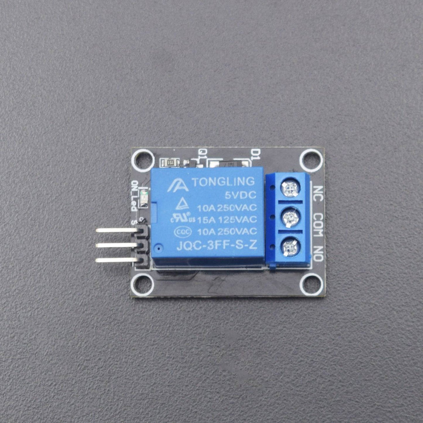
- 5V 1 Channel Relay Module - 1
- 220 V AC Bulb - 1
- Jumper Wire (male to female) - 40 pcs
- Jumper Wire (male to male) - 40 pcs
- Bulb holder -1
- 400 pt Breadboard -1
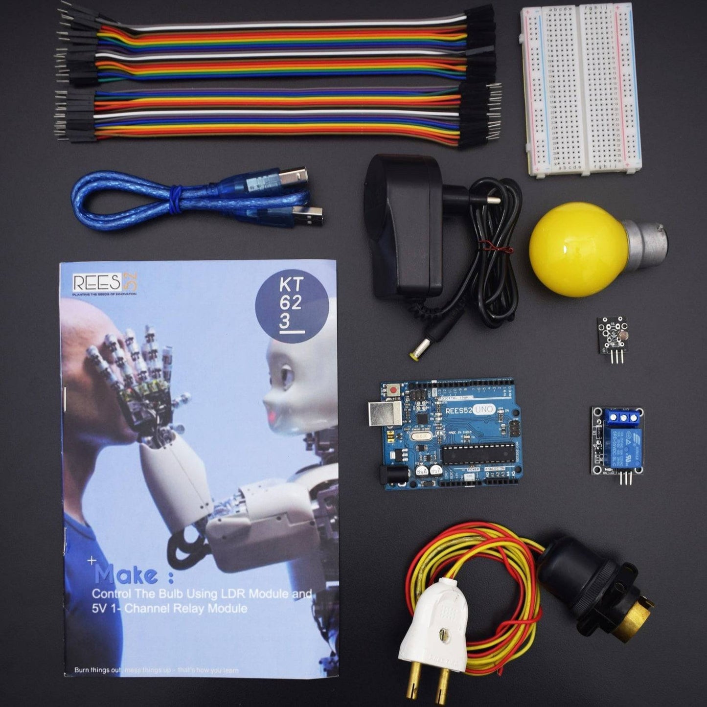
Introduction
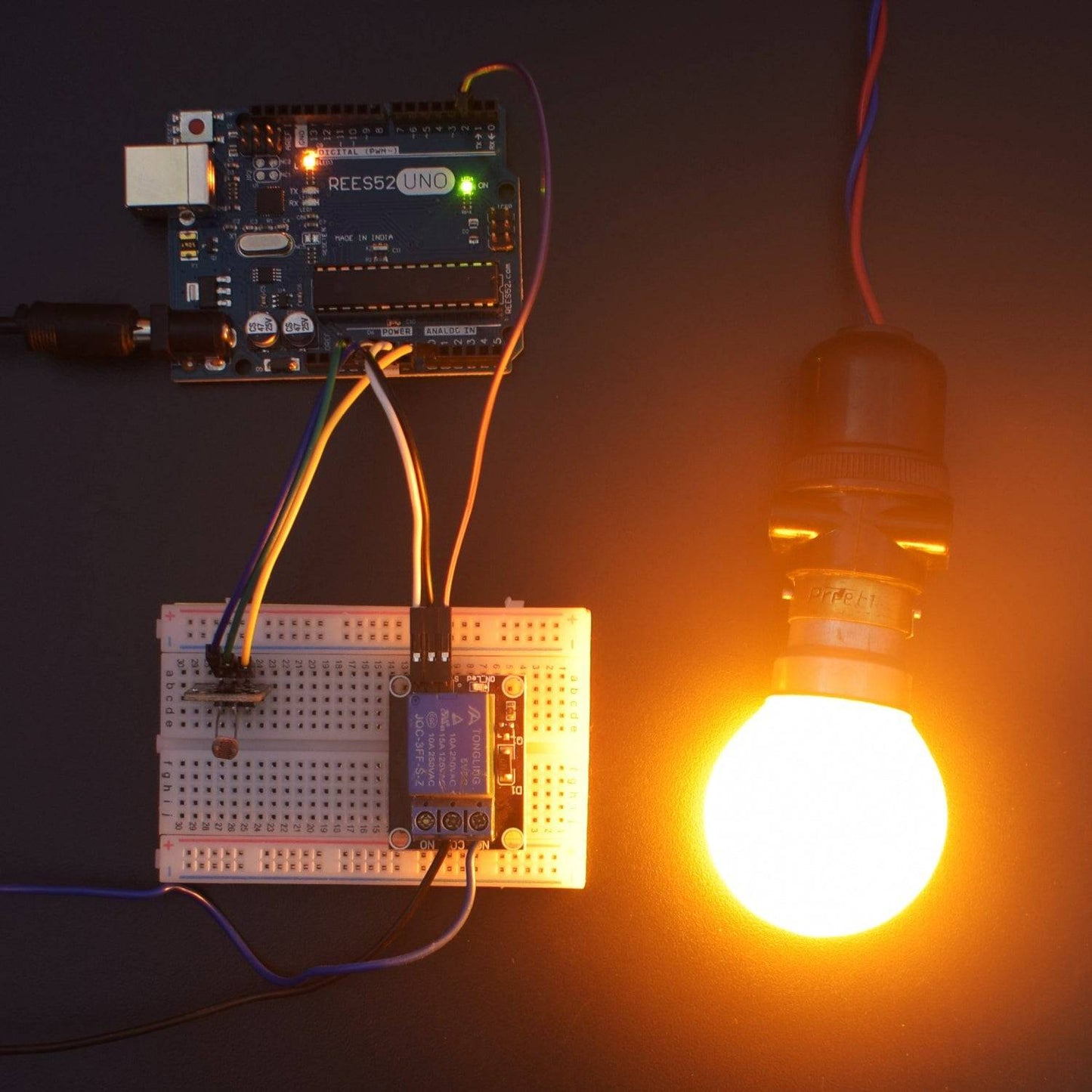
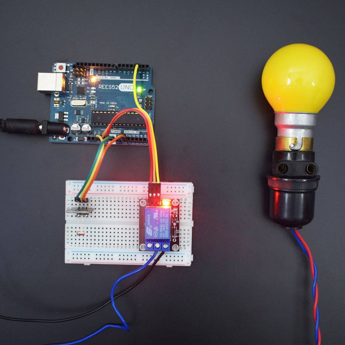
In this project, we will be controlling the Bulb using LDR module which will glow as Light Intensity on LDR Module decreases.
HARDWARE REQUIRED
- LDR Module - 1
- 12V 1A Adapter - 1
- Arduino Uno With USB Cable - 1
- Touch Sensor Module - 1
- 5V 1 Channel Relay Module - 1
- 220 V AC Bulb - 1
- Jumper Wire (male to female) - 40 pcs
- Jumper Wire (male to male) - 40 pcs
- Bulb holder -1
- 400 pt Breadboard -1
SOFTWARE REQUIRED
Arduino IDE 1.8.5 (programmable platform for Arduino)
Click To Download: https://www.arduino.cc/en/Main/Software
SPECIFICATIONS
.LDR Module
An LDR is a component that has a (variable) resistance that changes with the light intensity that falls upon it. This allows them to be used in light sensing circuits.
LDR has no polarity just like a resistor. The resistance of LDR can be very easily measured by just connecting the two terminals of LDR to a Multimeter & set the Multimeter on resistance Mode. It consists of a photoresistor and a 10kΩ in-line resistor. The photo resistor’s resistance will decrease in the presence of light and an increase in the absence of it. The output is analog and determines the intensity of light.
- Operating Voltage: 3.3V to 5V
- Output Type: Analog

5V 1 Channel Relay Module
- Number of I/O Channels: 1
- Type: Digital
- Control signal: TTL level
- Max. Allowable Voltage: 250VAC/110VDC
- Max. Allowable Power Force: From C(800VAC/240W), From A(1200VA/300W)


CIRCUIT CONNECTION
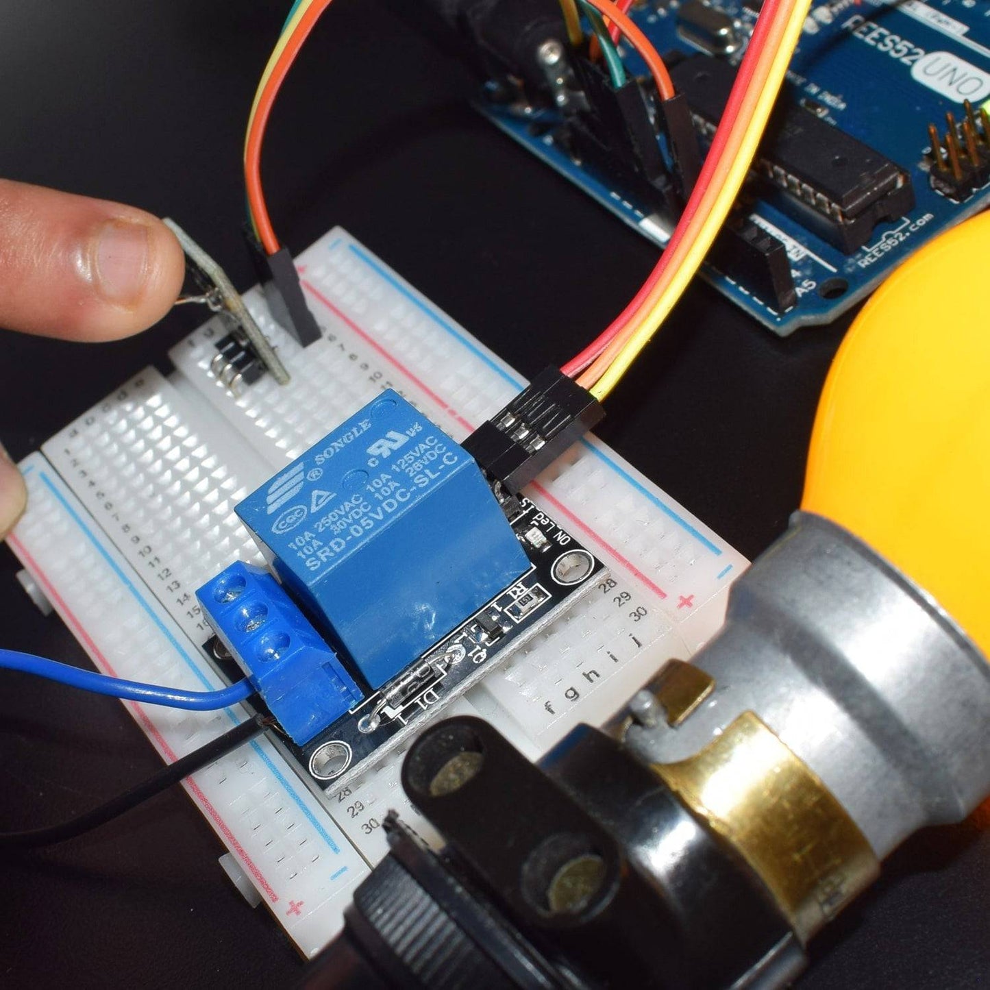
- Connect GND of Relay with GND of Arduino Uno.
- Connect VCC of Relay with Pin 5V of Arduino Uno.
- Connect Pin Signal of Relay with Digital Pin 2 of Arduino Uno.
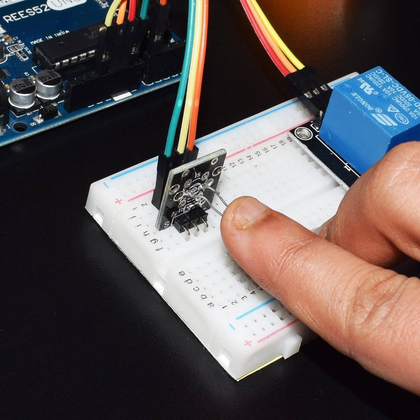
- Connect GND of LDR Module with GND of Arduino Uno.
- Connect VCC of LDR Module with Pin 3.3V of Arduino Uno.
- Connect Pin Signal of LDR Module with Analog Pin A0 of Arduino.
- Connect one terminal of Bulb (Blue Wire) with Pin NC (Normally Close) of Relay.
- Connect one terminal of Adapter with Pin C (Common) of Relay.
- Connect the other terminal of Bulb (Red Wire) with another terminal of the adapter.

CODE
Code for testing LDR Module:
https://drive.google.com/open?id=1FQww5oYpYGMmf3GpGB2OTeCaO-G5-3Q_
Code for working of LDR with Relay:
https://drive.google.com/open?id=1T1FjBq3GyI6ncL1DBt3eqplK-YZIPA5Q
WORKING
Welcome to the Arduino Based Project which consists of LDR Module and Relay. The basic functionality of LDR module is being described here. In order to detect the intensity of light or darkness, we use a sensor called an LDR (light dependent resistor). The LDR is a special type of resistor that allows higher voltages to pass through it (low resistance) whenever there is a high intensity of light, and passes a low voltage (high resistance) whenever it is dark. It is the project using an Arduino that automatically turn lights on when an LDR sensor detects darkness. Whenever a room gets dark due to a fused bulb or any other factors, a light bulb automatically turns on. You can even use this as an emergency lighting system. Use it to automatically turn a light on when there isn’t sufficient light in a room.
After connecting the LDR to your Arduino, you can check for the values coming from the LDR via the Arduino.