


vendor-unknown
Control a led using infrared sensor and give command by IR Remote interfacing with Arduino Uno - KT929
Control a led using infrared sensor and give command by IR Remote interfacing with Arduino Uno - KT929
SKU:KT929
1000 in stock
Couldn't load pickup availability
- For Bulk Order Click Here
- Need Customer Support?
- Free Delivery Above 999/-
Note: In case you receive a damaged or faulty product, please return it in the original box with all foam and packaging. Returns will not be accepted if further damage occurs due to improper packing.
If you order a product that is currently in Preorder, and the price of that item increases in the future, you will be required to pay the difference in price.
For refund/return/replacement, call us at +91 95995 94520 or email us at support@rees52.com
Delivery Time
Delivery Time
- Delivery time with the Express Shipping option is 2-3 working days, and with the Standard Shipping option is 5-6 working days. It varies based on location, reliant on courier services.
- Delivery time if the order item is on Preorder Status is 15-20 working days.
COD (Cash on Delivery)
COD (Cash on Delivery)
- For COD you have to pay extra charges of Rs 350/- before the shipment. (We will share the company QR Code, UPI ID or Account details for the same)

This Arduino project that allows to turn ON and OFF LEDs using a cheap IR remote
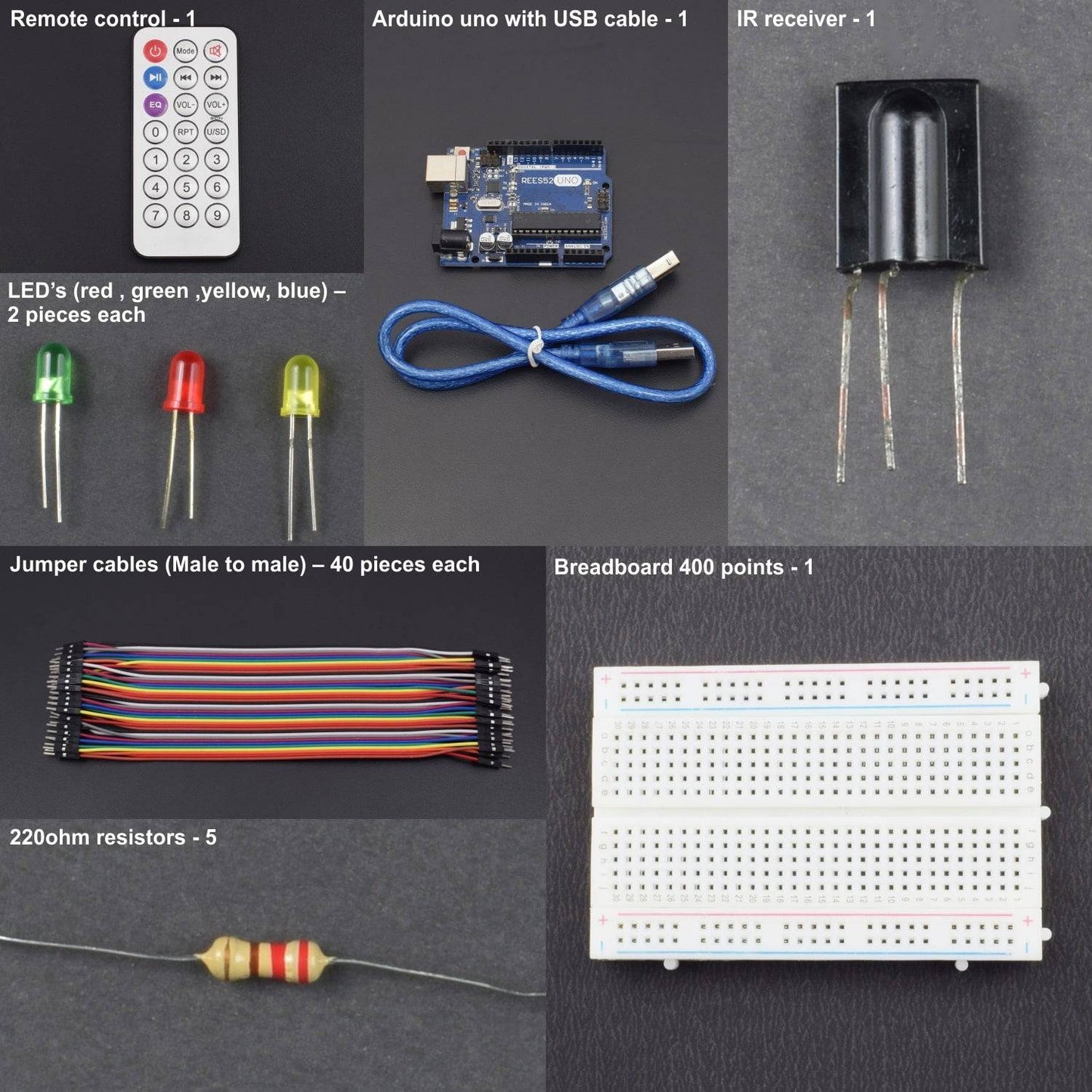
- Arduino uno with USB cable - 1
- Breadboard 400 points - 1
- Remote control - 1
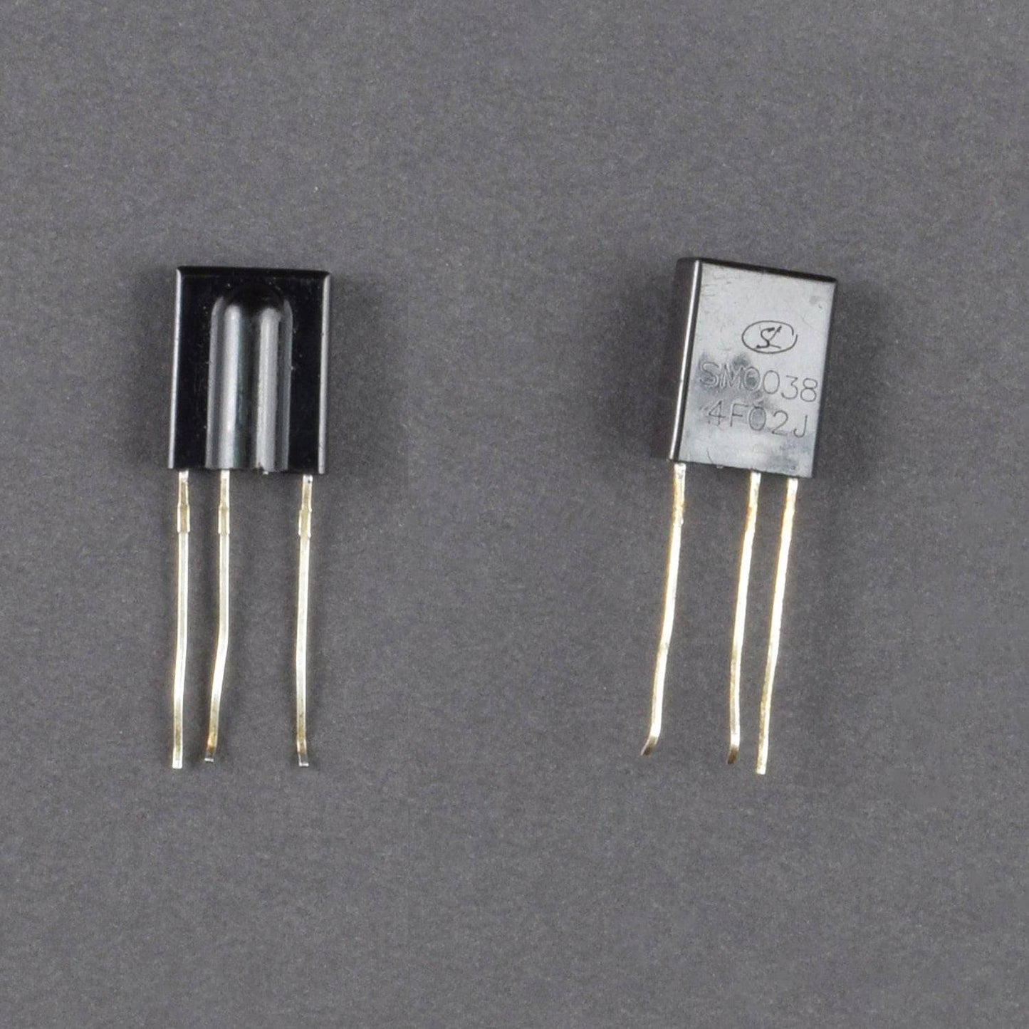
- IR receiver - 1
- LED’s (red ) – 2 pieces
- LED’s (green ) – 2 pieces
- LED’s (yellow) – 2 pieces
- LED’s ( blue) – 2 pieces
- 220ohm resistors - 5
- Jumper cables (Male to male) – 40 pieces
HARDWARE REQUIRED
- Arduino uno with USB cable - 1
- Breadboard 400 points - 1
- Remote control - 1
- IR receiver - 1
- LED’s (red ) – 2 pieces
- LED’s (green ) – 2 pieces
- LED’s (yellow) – 2 pieces
- LED’s ( blue) – 2 pieces
- 220ohm resistors - 5
- Jumper cables (Male to male) – 40 pieces
SOFTWARE REQUIRED
Arduino IDE 1.8.5 (programmable platform for Arduino)
Click To Download: https://www.arduino.cc/en/Main/Software


INSTALL LIBRARY
First, go to this page given below as link
https://github.com/RuiSantosdotme/Arduino-IRremote
and download this Library.
After downloading it, Extract the downloaded file in the Arduino’s library folder wherever you install the Arduino Software.
First, you need to check the Set the Remote to get the hexadecimal code.
For this we make the Receiver’s Connections as follows:
- The Receiver signal output will be connected to digital pin 11 of the Arduino
- The Receiver VCC(middle output) will be connected to digital pin +5v of the Arduino
- The Receiver GROUND output will be connected to digital pin ground of the Arduino
Open the Arduino IDE Software. Making these Connections,
Follow the instructions As given in the picture given below:
Click on IRrecvDumpV2 ,you will get a code and Upload the Code.

After Uploading the code , Just open the serial Monitor(ctrl+shift+m).
About Hex code :First we must find the hex codes of the buttons of remote controller.
Now press the buttons which you want to use in your project,here we are using 1,2,3 and OK button.
PRess the button(1,2,3&OK) you will get the hexadecimal Code(in red mark)
Then just need to change your remote control values from my arduino code.now convert the hexadecimal to decimal and change value in the code.
Values Are:

case your value decimal after conversion change all the four cases in the Code given below and upload the code.
PIN DESCRIPTION
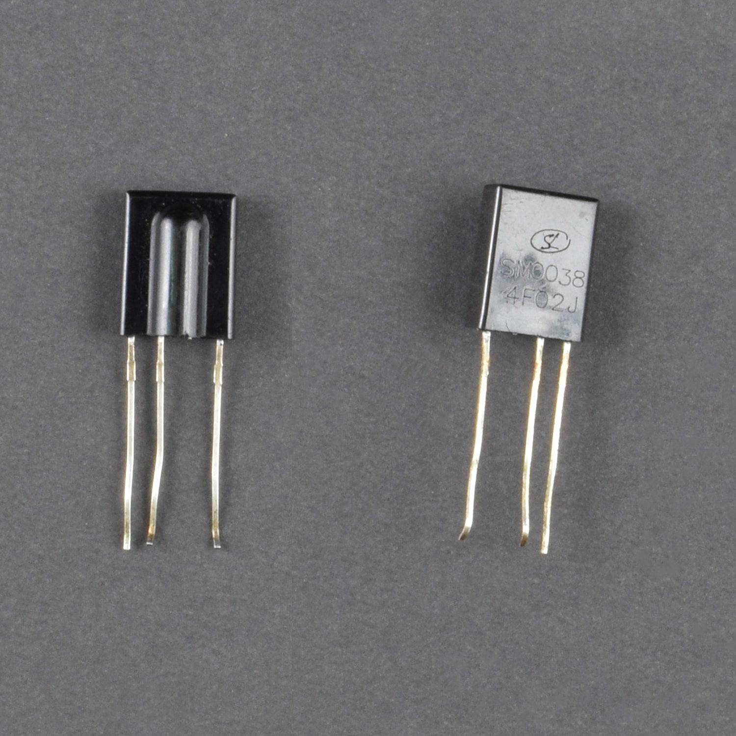
Infrared Receiver Pin
- First pin: Vout, outputs HIGH when no signal is present and LOW when a mark is received.
- Second pin: GND.
- Third pin: VCC

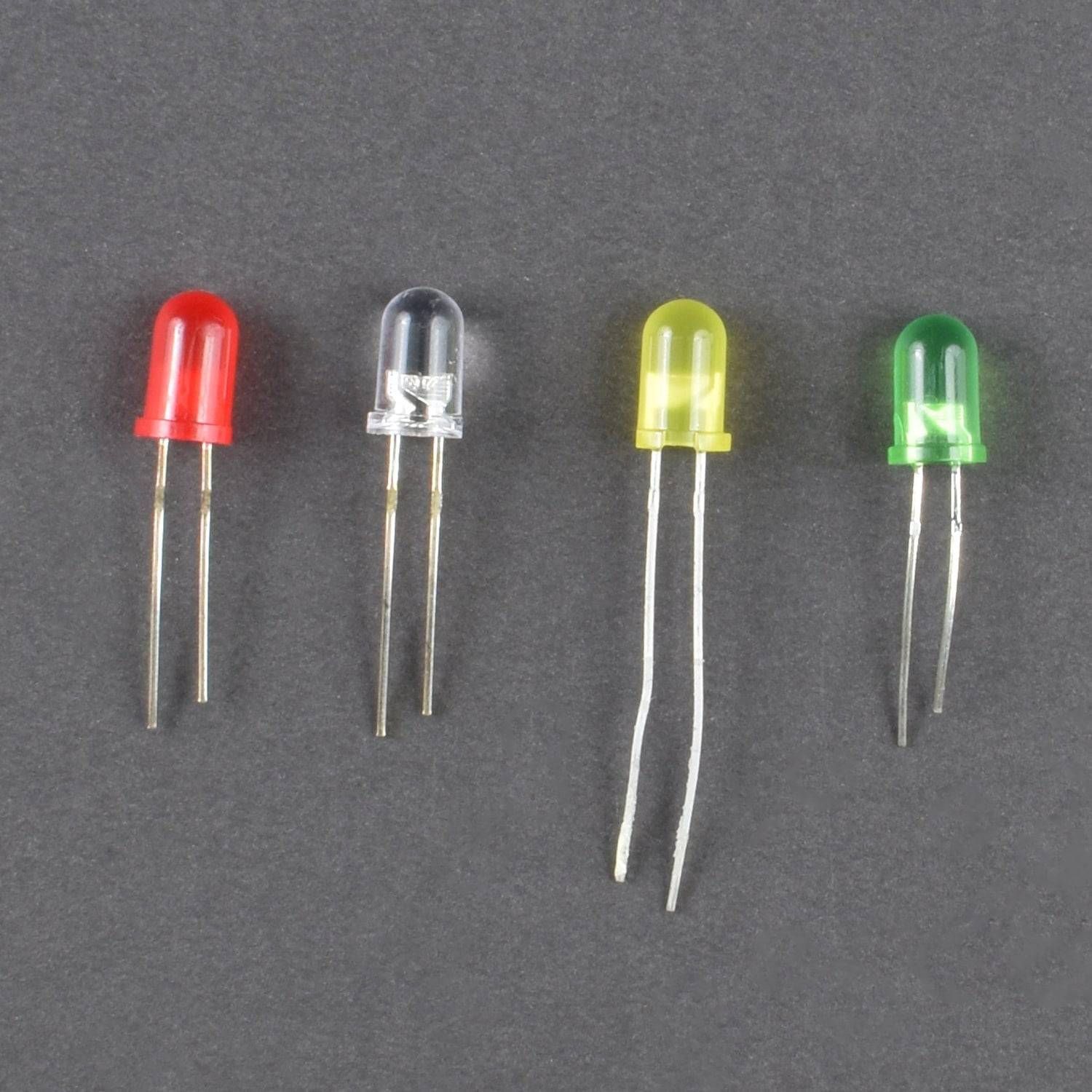
LED


How to check the Positive and negative terminal of the Led?
The Shorter leg is cathode(Negative) and the Longer leg is anode (positive)
In the bulb ,bigger flag is negative and shorter flag is positive
On the bulb surface , the flat surface is negative and rounded surface is positive
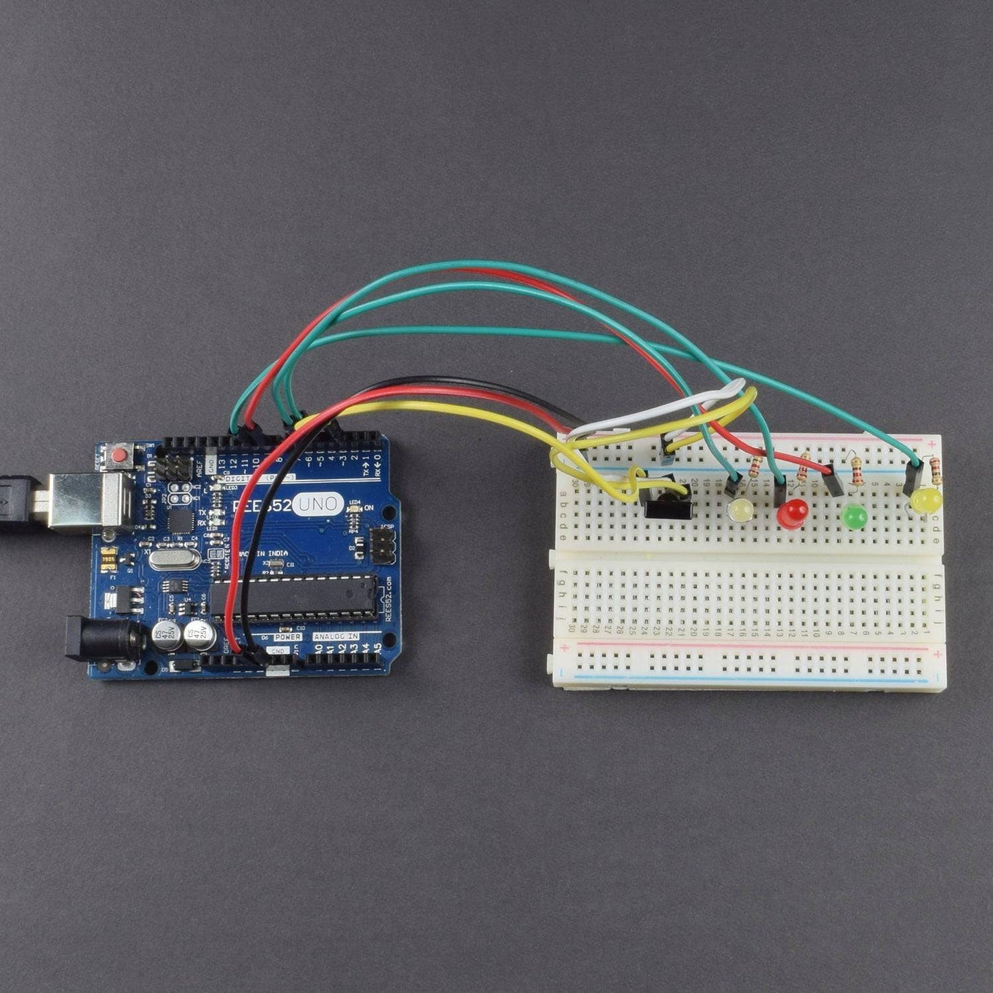
CIRCUIT DESCRIPTION

1. Arduino ground goes to breadboard negative.
2. Arduino 5v goes to infrared sensor supply pin.
3. infrared sensor 2pin goes ground of bread board.
4. infrared sensor 3pin goes to the digital pin no3 of Arduino Uno.
5. led green positive connect to digital pin 5 of Arduino Uno.
6. led yellow positive connectto digital pin 6 of Arduino Uno.
7. led red positive connectto digital pin 9 of Arduino Uno.
8. led white positive connectto digital pin 10 of Arduino Uno.
all negative pin of led connect with 220 ohm resistance on bread board.
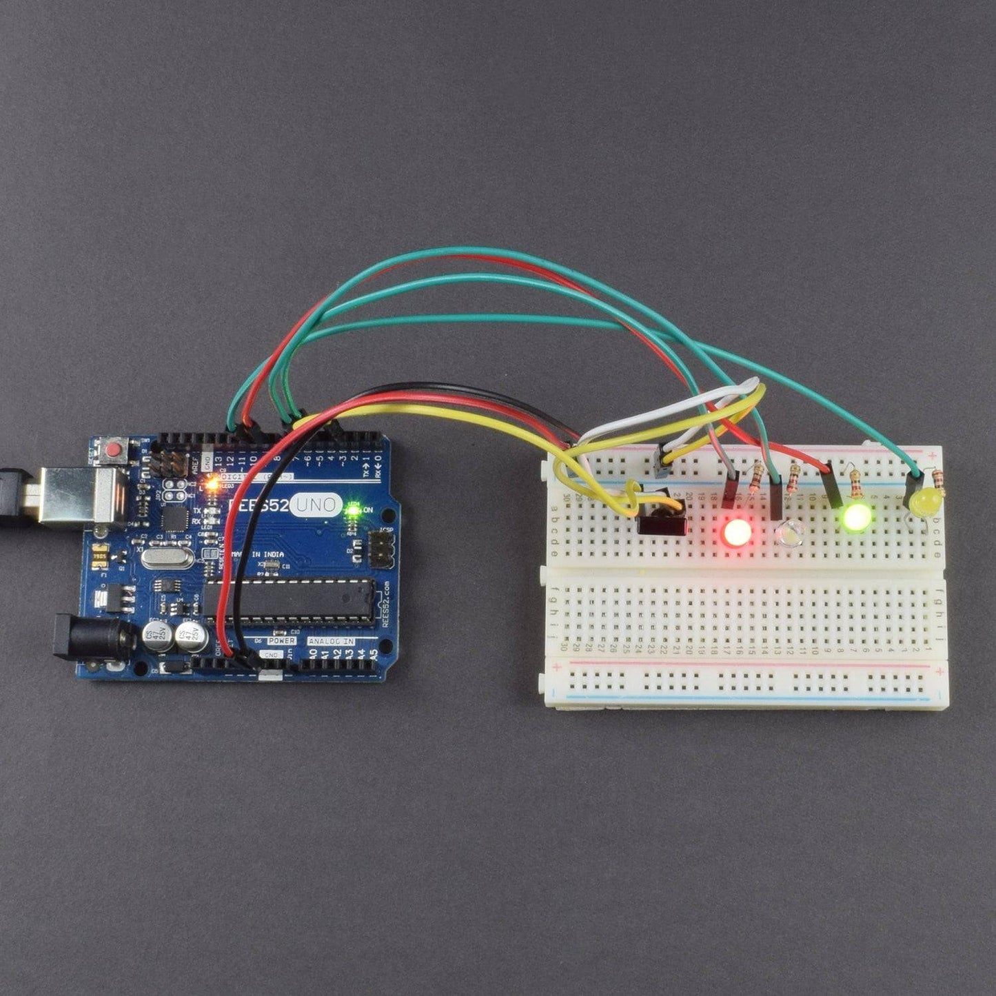
- Press the button 1,first led will glow
- Button 2, second led will glow
- Button 3,third led will glow
- Button OK, all led’s will turn off.
CODE
WORKING
If you want to decode code of a remote controller, you must first know how it's coded. The coding method we use here is NEC protocol. Below is a brief introduction. ·NEC protocol:
Features:
- 8 bit address and 8 bit command length
- address and command are transmitted twice for reliability
- pulse distance modulation
- carrier frequency of 38 KHZ
- Bit time of 1.125ms or 2.25ms
Protocol is as below:
- Definition of logical 0 and 1 is as below

- Pulse transmitted when the button is pressed and immediately released.

The picture above shows a typical pulse train of the NEC protocol. With this protocol the LSB is transmitted first. In this case Address $59 and Command $16 is transmitted. A message is started by a 9ms AGC burst, which was used to set the gain of the earlier IR receivers. This AGC burst is then followed by a 4.5ms space, which is then followed by the address and command. Address and Command are transmitted twice. The second time all bits are inverted and can be used for verification of the received message. The total transmission time is constant because every bit is repeated with its inverted length. If you are not interested in this reliability, you can ignore the inverted values, or you can expend the Address and Command to 16 bits each!
- Pulse transmitted when button is pressed and released after a period of time

A command is transmitted only once, even when key on the remote
Control remains pressed. Every 110ms a repeat code is transmitted
for as long as the key remains down. This repeat code is simply a 9ms AGC pulse followed by a 2.25ms space and a 560µs burst.
- Repeat pulse

Note: when the pulse enters the integrated receiver, there will be decoding, the signal amplifying and wave shaping process. So you need to make sure the level of the output is just the opposite from that of the signal sending end. That is when there is no infrared signal, the output end is at high level; when there is an infrared signal, and output end is in low level.
You can see the pulse of the receiving end in the oscilloscope. Decode the coded pulse signal emitted by the remote controller; execute corresponding action according to the results of the decoding. In this way, you will be able to control your device with a remote controller.