


Generic
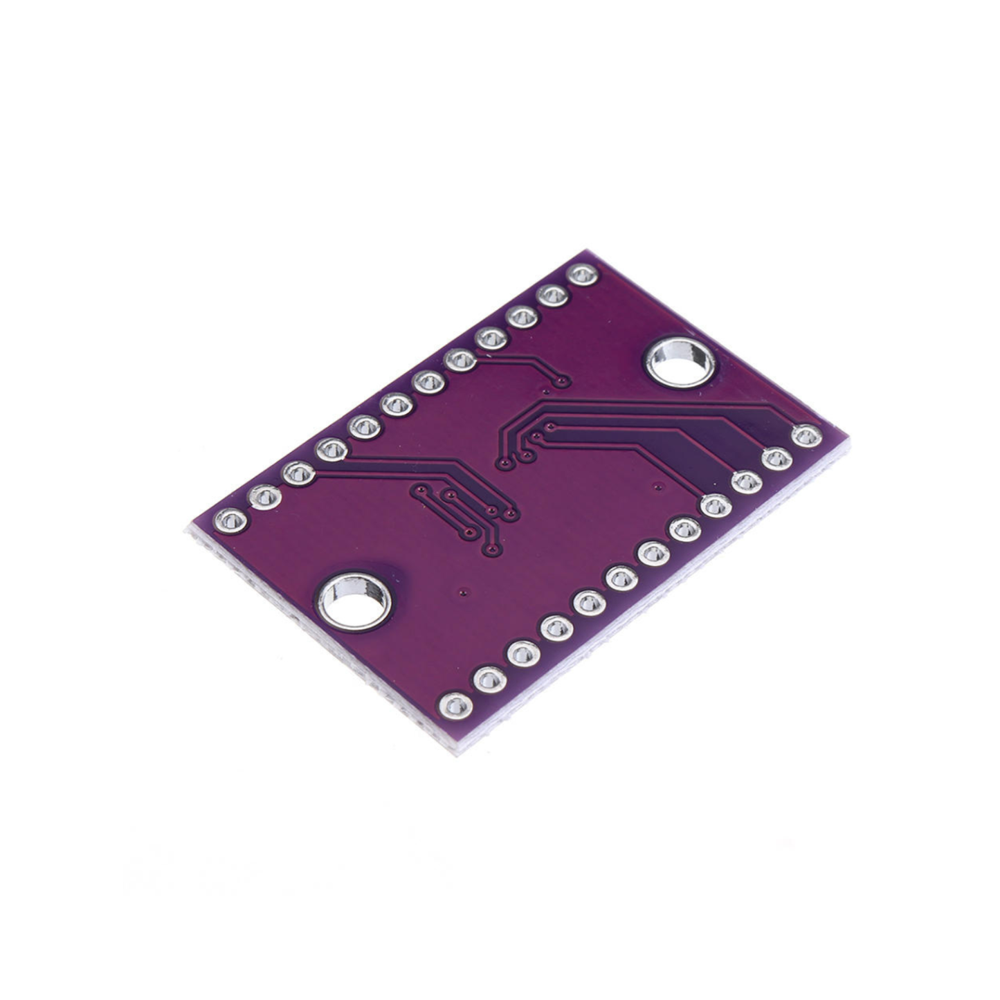
TCA9548A 1-to-8 I2C Multiple Extensions Board CJMCU-9548 IIC 8-Channel Development For DIY Projects - RS1976
TCA9548A 1-to-8 I2C Multiple Extensions Board CJMCU-9548 IIC 8-Channel Development For DIY Projects - RS1976
SKU:RS1976
43 in stock
Couldn't load pickup availability
- For Bulk Order Click Here
- Need Customer Support?
- Free Delivery Above 999/-
Note: In case you receive a damaged or faulty product, please return it in the original box with all foam and packaging. Returns will not be accepted if further damage occurs due to improper packing.
For refund/return/replacement, call us at +91 95995 94520 or email us at support@rees52.com
Delivery Time
Delivery Time
- Delivery time with the Express Shipping option is 2-3 working days, and with the Standard Shipping option is 5-6 working days. It varies based on location, reliant on courier services.
- Delivery time if the order item is on Preorder Status is 15-20 working days.
COD (Cash on Delivery)
COD (Cash on Delivery)
- For COD you have to pay extra charges of Rs 350/- before the shipment. (We will share the company QR Code, UPI ID or Account details for the same)


Description:
The CJMCU TCA9548A I2C 8-Channel Multiple Extensions Development Board is an advanced I2C multiplexer designed to expand your project’s capability by allowing you to control up to eight different I2C devices with a single microcontroller. With its compact design and straightforward interface, this board is perfect for applications that require the connection of multiple I2C devices, avoiding address conflicts. It’s ideal for use in projects involving sensors, displays, or other I2C peripherals.
Specification:
- Model No: CJMCU TCA9548A
- No. of Channels: 8
- Input Voltage: 1.6~5.5V
- Clock Frequency: 0~400kHz
Features:
- 1-to-8 Bidirectional Switches
- Hot Insertion Support
- Low Standby Current
- Active-Low Reset Input
- Power Up with Deselected Channels
- I2C/SMBus Compatible
- 5V Tolerant Inputs
- Exceeds 100mA Latch-Up Performance (JESD 78, Class II)
Pin Description:
Power Pins:
- Vin – this is the power pin. Since the sensor chip uses 3-5 VDC. To power, the board, give it the same power as the logic level of your microcontroller – e.g. for a 5V micro like Arduino, use 5V.
- GND – common ground for power and logic.
I2C Control-Side Pins:
- SCL – this is the I2C clock pin for the chip itself, connected to your microcontroller's I2C clock line.
- SDA is the I2C data pin for the chip itself, connected to your microcontroller's I2C data line.
- RST is the reset pin for resetting the multiplexer chip. Pulled high by default; connect to ground to reset
- A0, A1, A2 – these are the address selection pins for the multiplexer. By default, the multiplexer is at address 0x70, and these three pins are pulled low. Connect them to Vin to set the address to 0x71 – 0x77.
- A0 is the lowest-significant bit (if it is pulled high, it will increase the address by 1).
- A1 is the 2nd-lowest-significant bit (if it is pulled high, it will increase the address by 2).
- A2 is the 3rd-lowest-significant bit (if it is pulled high, it will increase the address by 4).
I2C Multiplexed-Side Pins:
- SDx and SCx: There are 8 sets of SDx and SCx pins, from SD0/SC0 to SD7/SC7. These are the multiplexed pins. Each one is a completely separate I2C bus set. So you have 8 I2C devices with identical addresses, as long as they are on one I2C bus each.
- These pins do not have any pull-ups installed, so if you are using a chip or breakout without I2C pull-ups, be sure to add them! Nicely, you can have Vin be 3.3V and have these pins pulled up to 5V (that is, they are 5V-compliant).
Package Included:
1 x TCA9548A 1-to-8 I2C Multiple Extensions Board