


vendor-unknown
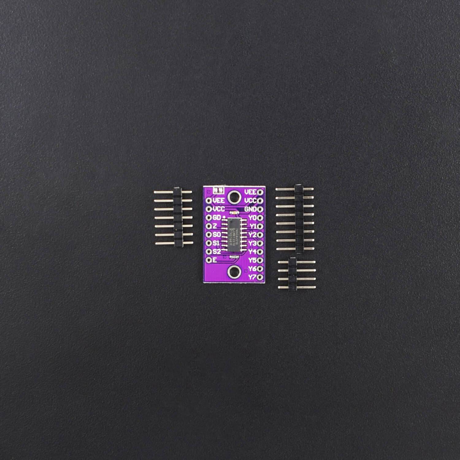
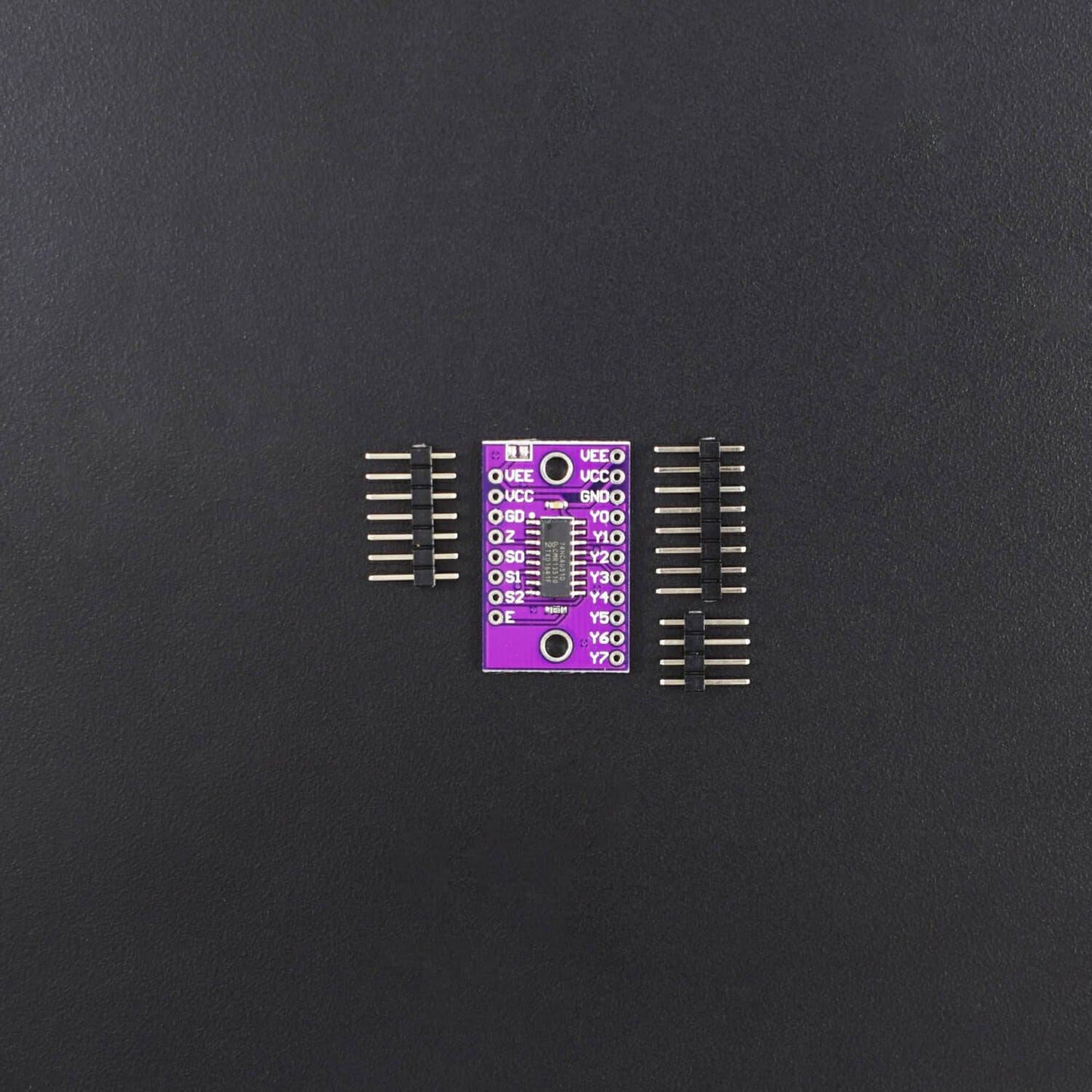
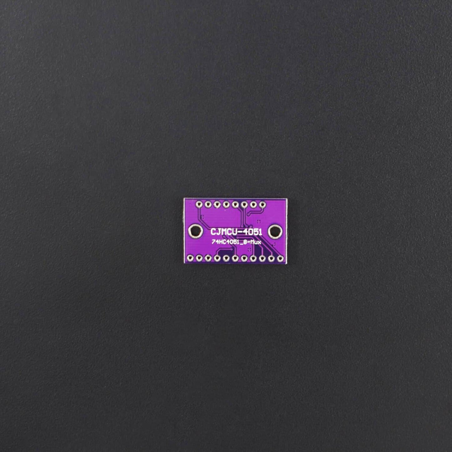
CJMCU - 4051 74HC4051 8-Channel-Mux Analog Multiplexer/ Demultiplexer Breakout Board Multiplexer Module -RS1973/RS3860
CJMCU - 4051 74HC4051 8-Channel-Mux Analog Multiplexer/ Demultiplexer Breakout Board Multiplexer Module -RS1973/RS3860
SKU:RS1973/RS3860
35 in stock
Couldn't load pickup availability
- For Bulk Order Click Here
- Need Customer Support?
- Free Delivery Above 999/-
Note: In case you receive a damaged or faulty product, please return it in the original box with all foam and packaging. Returns will not be accepted if further damage occurs due to improper packing.
If you order a product that is currently in Preorder, and the price of that item increases in the future, you will be required to pay the difference in price.
For refund/return/replacement, call us at +91 95995 94520 or email us at support@rees52.com
Delivery Time
Delivery Time
- Delivery time with the Express Shipping option is 2-3 working days, and with the Standard Shipping option is 5-6 working days. It varies based on location, reliant on courier services.
- Delivery time if the order item is on Preorder Status is 15-20 working days.
COD (Cash on Delivery)
COD (Cash on Delivery)
- For COD you have to pay extra charges of Rs 350/- before the shipment. (We will share the company QR Code, UPI ID or Account details for the same)

- Wide analogue input voltage range from -5 V to +5 V
- Complies with JEDEC standard no. 7A
- Low ON resistance:
- 80 ohm (typical) at VCC - VEE = 4.5 V
- 70 ohm(typical) at VCC - VEE = 6.0 V
Description:
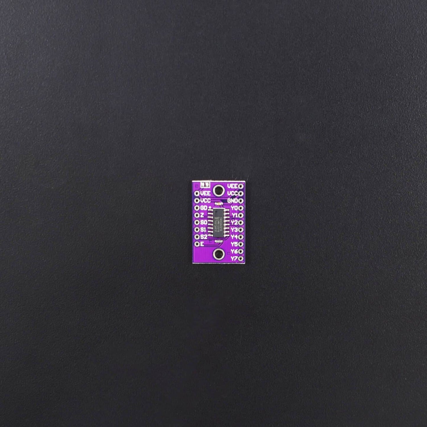
This is CJMCU-4051 74HC4051 8 Channel Analog Multiplexer/Demultiplexer Sensor Module Breakout Board for Arduino. 74HCT4051 is a single-pole octal-throw analogue switch (SP8T) suitable for use in analogue or digital 8:1 multiplexer/demultiplexer applications. The switch features three digital select inputs (S0, S1, and S2), eight independent inputs/outputs (Yn), a common input/output (Z) and a digital enable input (E). When E is HIGH, the switches are turned off. Inputs include clamp diodes. This enables the use of current limiting resistors to interface inputs to voltages in excess of VCC.
Specification:
- Wide analogue input voltage range from -5 V to +5 V
- Complies with JEDEC standard no. 7A
- Low ON resistance:
- 80 ohm (typical) at VCC - VEE = 4.5 V
- 70 ohm(typical) at VCC - VEE = 6.0 V
- 60 ohm(typical) at VCC - VEE = 9.0 V
- Logic level translation: to enable 5 V logic to communicate with±5 V analogue signals
- Specified from -40℃ to +85℃ and -40℃ to +125℃
Features:
- 1-to-8 Bidirectional Translating Switches.
- Supports Hot Insertion.
- Low Standby Current.
- 1-to-8 Bidirectional Translating Switches.
- Active-Low Reset Input.
- Power Up With All Switch Channels Deselected.
- I2C Bus and SMBus Compatible.
- 5-V Tolerant Inputs.
- Latch-Up Performance Exceeds 100 mA Per JESD 78, Class II.
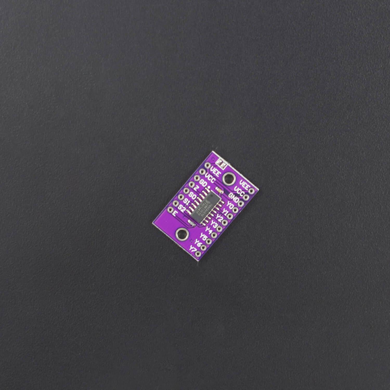
Pin Description:
Power Pins:
- Vin: This is the power pin. Since the sensor chip uses 3-5 VDC. To power, the board, give it the same power as the logic level of your microcontroller – e.g. for a 5V micro like Arduino, use 5V.
- GND: Common ground for power and logic.
I2C Control-Side Pins:
- SCL: This is the I2C clock pin for the chip itself, connect to your microcontrollers I2C clock line.
- SDA: This is the I2C data pin for the chip itself, connect to your microcontrollers I2C data line.
- RST: This is the reset pin, for resetting the multiplexer chip. Pulled high by default, connect to ground to reset
- A0 A1 A2: These are the address selection pins for the multiplexer. By default, the multiplexer is at address 0x70 and these three pins are pulled low. Connect them to Vin to set the address to 0x71 – 0x77.
- A0 is the lowest-significant bit (if it is pulled high, it will increase the address by 1).
- A1 is the 2nd-lowest-significant bit (if it is pulled high, it will increase the address by 2).
- A2 is the 3rd-lowest-significant bit (if it is pulled high, it will increase the address by 4).
I2C Multiplexed-Side Pins:
- SDx and SCx: There are 8 sets of SDx and SCx pins, from SD0/SC0 to SD7/SC7. These are the multiplexed pins. Each one is a completely separate I2C bus set. So you have 8 I2C devices with identical addresses, as long as they are on one I2C bus each.
- These pins do not have any pullups installed, so if you are using a chip or breakout without I2C pull-ups be sure to add them! Nicely, you can have Vin be 3.3V and have these pins pulled up to 5V (that is, they are 5V compliant).
Package Included:
1 x CJMCU - 4051 74HC4051 8-Channel-Mux Analog Multiplexer/ Demultiplexer Breakout Board Multiplexer Module