


vendor-unknown
Blink a Led using Hand’s clap - KT903
Blink a Led using Hand’s clap - KT903
SKU:KT903
1000 in stock
Couldn't load pickup availability
- For Bulk Order Click Here
- Need Customer Support?
- Free Delivery Above 999/-
For refund/return/replacement, call us at +91 95995 94520 , +91 95991 22209 or mail us at support@rees52.com
Delivery Time
Delivery Time
- Delivery time with the Express Shipping option is 2-3 working days, and with the Standard Shipping option is 5-6 working days. It varies based on location, reliant on courier services.
- Delivery time if the order item is on Preorder Status is 15-20 working days.
COD (Cash on Delivery)
COD (Cash on Delivery)
- For COD you have to pay extra charges of Rs 350/- before the shipment. (We will share the company QR Code, UPI ID or Account details for the same)


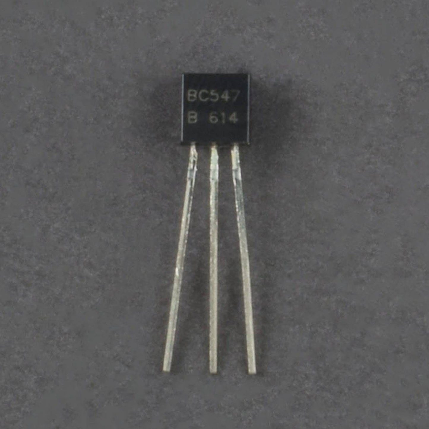
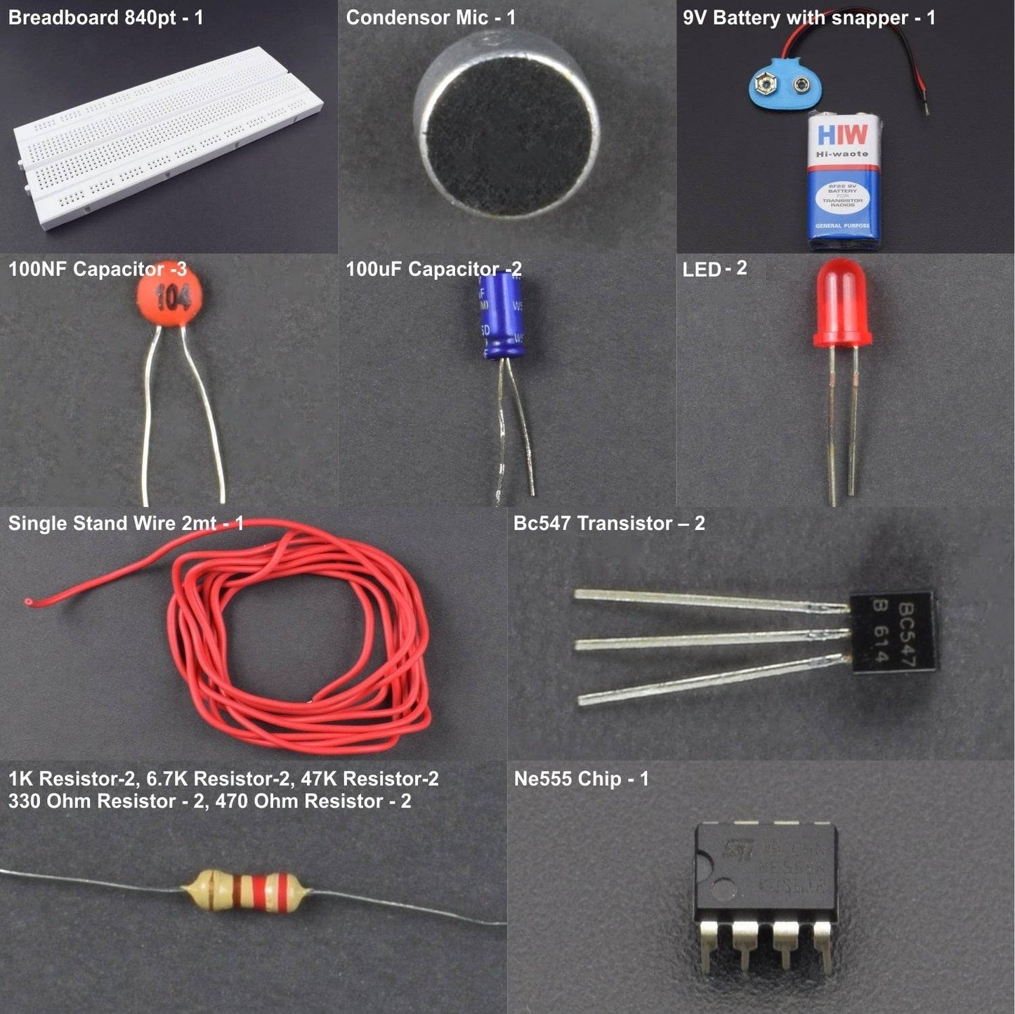
- BC547 Transistor – 2
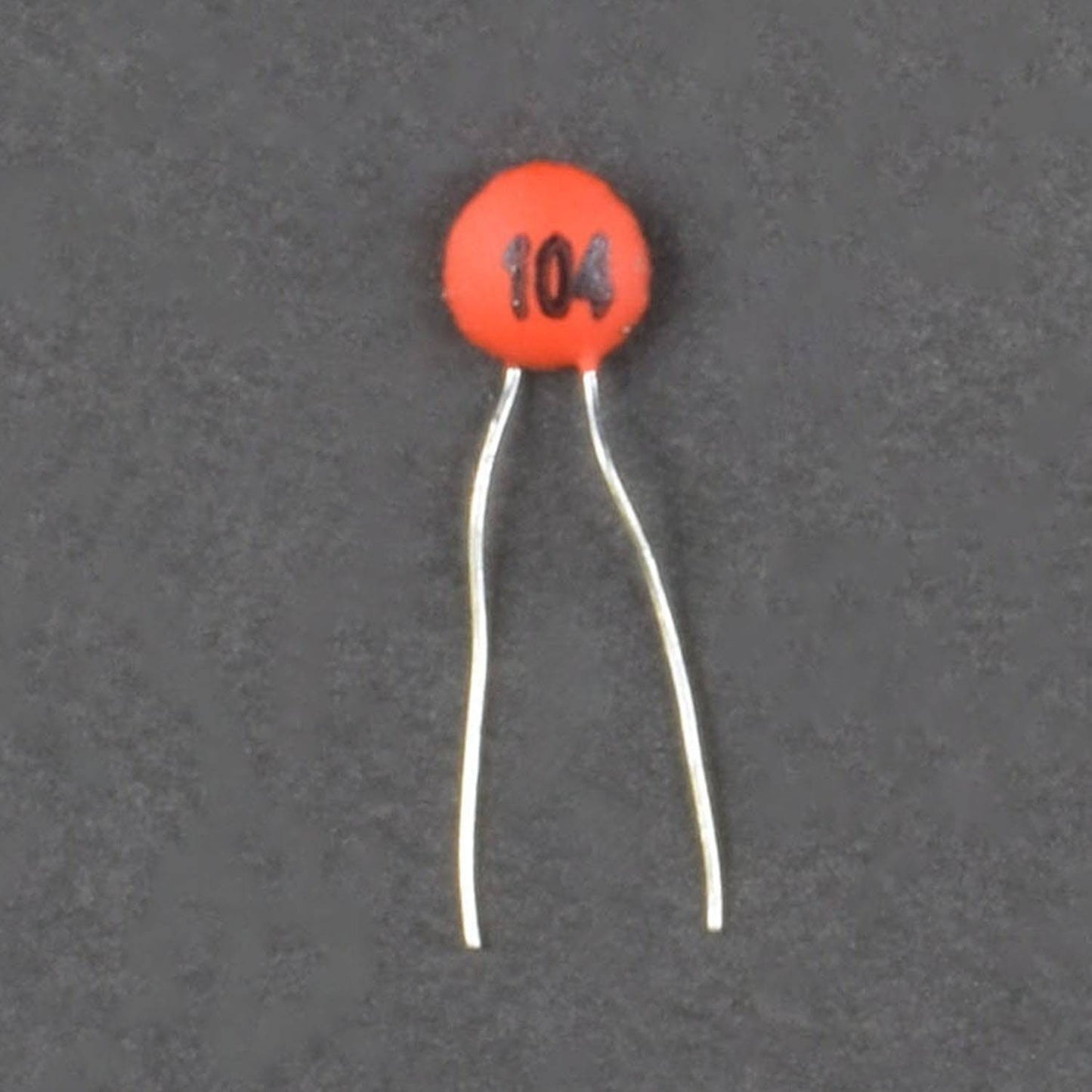
- 100NF Capacitor -3
- 100uF Capacitor -2
- 1K Resistor-2
- 6.7K Resistor-2
- 47K Resistor-2
- 330 Ohm Resistor - 2
- 470 Ohm Resistor - 2
- NE555 Chip - 1
- LED(Light Emitting Diode) blue- 2
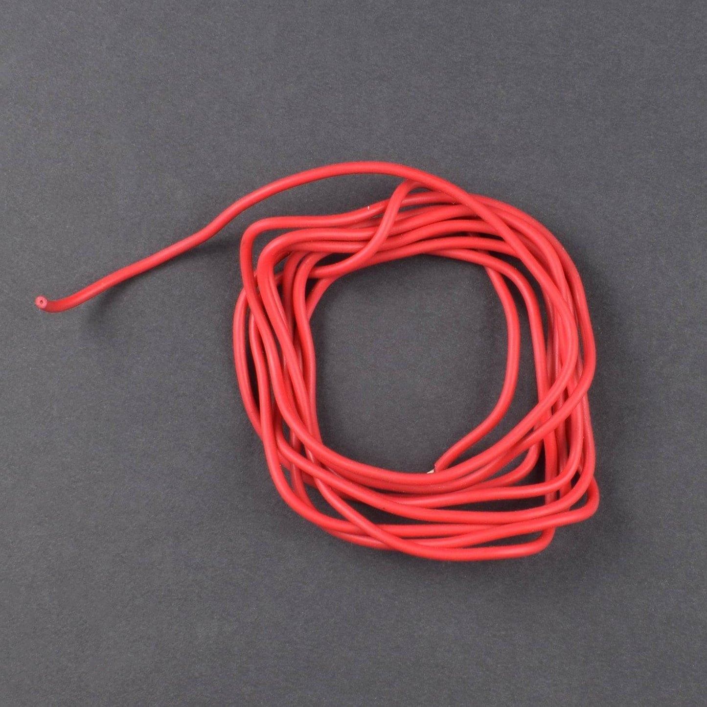
- Single stand wire 2m - 1
- Breadboard 840 points - 1
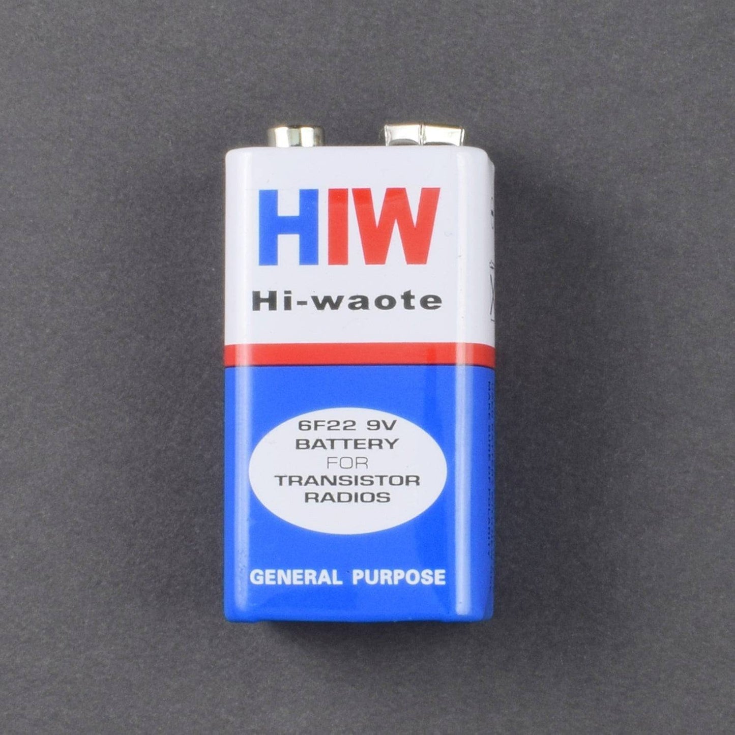
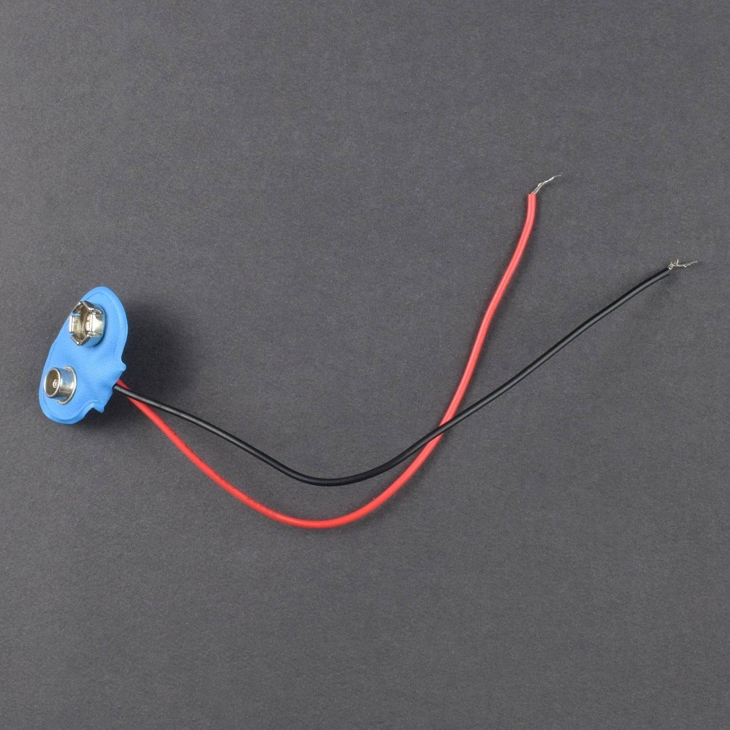
- 9V Battery with snapper – 1
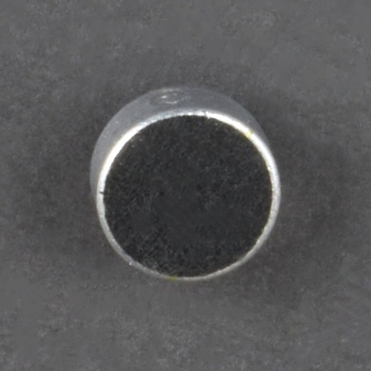
- Condenser Mic - 1
HARDWARE REQUIRED
- BC547 Transistor – 2
- 100NF Capacitor -3
- 100uF Capacitor -2
- 1K Resistor-2
- 6.7K Resistor-2
- 47K Resistor-2
- 330 Ohm Resistor - 2
- 470 Ohm Resistor - 2
- NE555 Chip - 1
- LED(Light Emitting Diode) blue- 2
- Single stand wire 2m - 1
- Breadboard 840 points - 1
- 9V Battery with snapper – 1
- Condenser Mic - 1
PIN DESCRIPTION
2 Colour Led module

2 Colour Led module

Pin |
Name |
Purpose |
1 |
GND |
Ground reference voltage, low level (0 V) |
2 |
TRIG |
The OUT pin goes high and a timing interval starts when this input falls below 1/2 of CTRL voltage (which is typically 1/3 Vcc, CTRL being 2/3 Vcc by default if CTRL is left open). In other words, OUT is high as long as the trigger low. Output of the timer totally depends upon the amplitude of the external trigger voltage applied to this pin. |
3 |
OUT |
This output is driven to approximately 1.7 V below +Vcc, or to GND. |
4 |
RESET |
A timing interval may be reset by driving this input to GND, but the timing does not begin again until RESET rises above approximately 0.7 volts. Overrides TRIG which overrides threshold. |
5 |
CTRL |
Provides “control” access to the internal voltage divider (by default, 2/3 Vcc). |
6 |
THR |
The timing (OUT high) interval ends when the voltage at threshold is greater than that at CTRL (2/3 Vcc if CTRL is open). |
7 |
DIS |
Open collector output which may discharge a capacitor between intervals. In phase with output. |
8 |
Vcc |
Positive supply voltage, which is usually between 3 and 15 V depending on the variation. |
Led

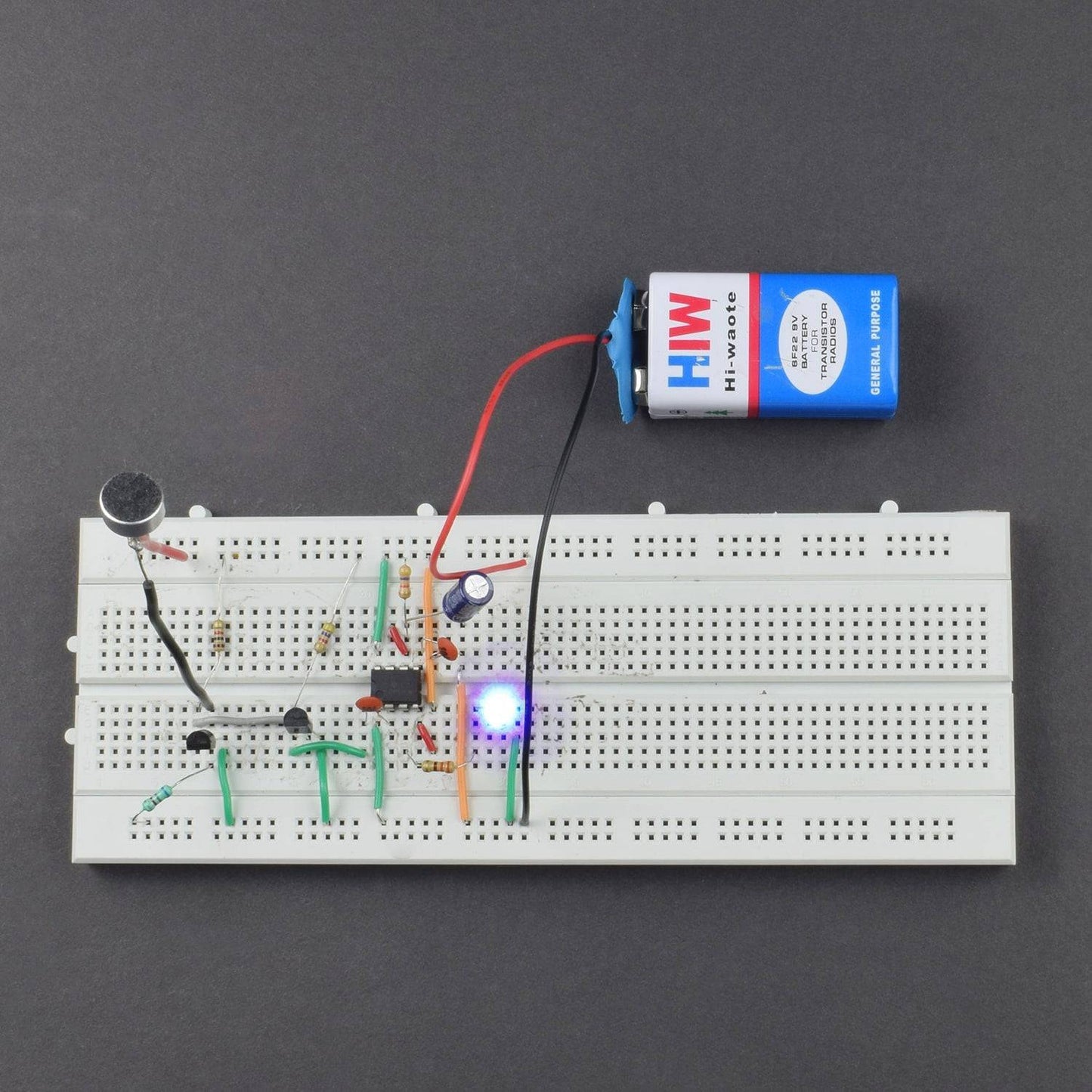
CIRCUIT DIAGRAM

- connect emitter of two BC547 TRANSISTOR to the negative rail of BREADBOARD
- connect the 6.7K RESISTOR from base of 1st BC547 to NEGATIVE rail
- connect the 1k Resistor from the collector of 1st BC547 to POSITIVE rail
- connect the collector of 1st bc547 to the base of 2nd bc547
- connect the 470 ohm resistor from the collector of the second bc547 to the POSITIVE rail
- connect pin 4 & 8 of 555ic to POSITIVE rail
- connect pin 6 of the 555ic to pin 7 of 555ic
- connect the 47k resistor from pin 6/ 7 of 555ic to the POSITIVE rail
- connect the NEGATIVE terminal of 100uf cap to NEGATIVE rail
- insert the other 0.1 uf cap on the breadboard with one terminal with pin 2 of 555ic
- insert the LED anode via 330 ohm resistor to pin 3 of 555ic and cathode with -ve rail
- insert the condenser POSITIVE to POSITIVE rail and NEGATIVE to base of 1st bc547
- connect the 9v battery to the breadboard.
OUTPUT
Whenever you clap by your hands, led will start blink.
*The glow time of led depend on the value of the capacitor if value is high then glow time will high and vice versa