


vendor-unknown
Basic Component Kit for School Kids for Science projects - KT580
Basic Component Kit for School Kids for Science projects - KT580
SKU:KT580
Low stock: 10 left
Couldn't load pickup availability
- For Bulk Order Click Here
- Need Customer Support?
- Free Delivery Above 999/-
Note: In case you receive a damaged or faulty product, please return it in the original box with all foam and packaging. Returns will not be accepted if further damage occurs due to improper packing.
If you order a product that is currently in Preorder, and the price of that item increases in the future, you will be required to pay the difference in price.
For refund/return/replacement, call us at +91 95995 94520 or email us at support@rees52.com
Delivery Time
Delivery Time
- Delivery time with the Express Shipping option is 2-3 working days, and with the Standard Shipping option is 5-6 working days. It varies based on location, reliant on courier services.
- Delivery time if the order item is on Preorder Status is 15-20 working days.
COD (Cash on Delivery)
COD (Cash on Delivery)
- For COD you have to pay extra charges of Rs 350/- before the shipment. (We will share the company QR Code, UPI ID or Account details for the same)

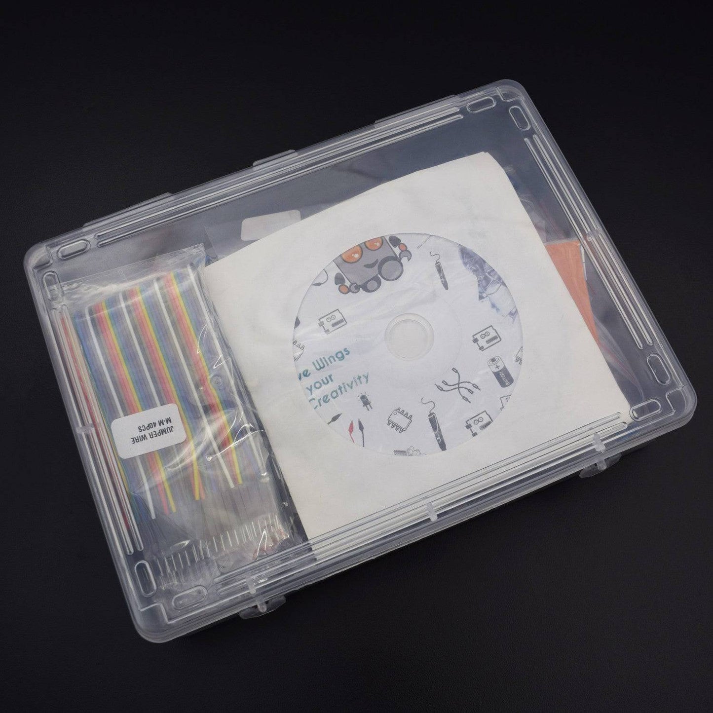
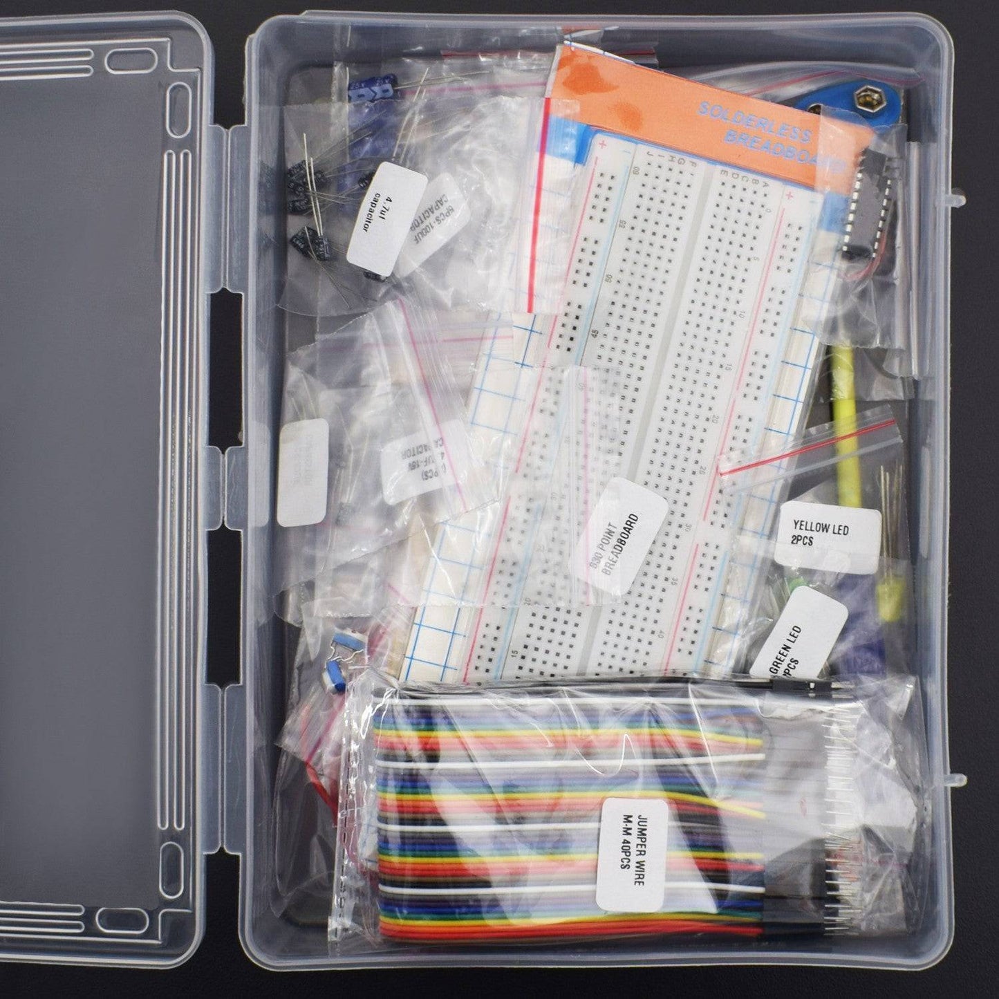
This is the Basic Component kit for School Kids. They can make various project using this component kit. This kit includes Various types of Resistors, Capacitors & Led etc.
Check out the Playlist :
https://www.youtube.com/watch?v=ws-727vGnS8&list=PLeZjSVeikamNBPNZaF-ojoB43qpPjSFuR

PACKAGE INCLUDED
| Product name | Qty |
| 555 Timer IC | 2 |
| B-10 Buzzer | 1 |
|
Capacitor Electrolytic(47uf (25v) - 2 47uf (50v) -2, 4.7uf (16v)- 2) Ceramic(0.1 uf -2 , 100 uf - 2 & 0.01 uf - 2) |
|
| Resistor (10k - 5 , 470k - 5, 100R - 5 , 1M - 5 , 1k - 5 , 330R - 5 , 220R - 5 , 22K - 5, 47K - 5, 2.2K - 5 , 470R - 5 & 33K - 5 ) | |
| Breadboard 830 pt | 1 |
| Single Stand Wire 2mt | 1 |
| 9v Battery | 1 |
| Battery Snapper | 1 |
| Jumper wire (male to Male) - 40 pcs | 1 |
| Transistor (BC547 ) | 7 |
| Led (each colour) | 10 |
| CD4017 IC | 2 |
| Push button | 2 |
| Screw Driver | 1 |
| 10K Pot | 2 |
PROJECT LIST
PRODUCT DESCRIPTION
LED

NE555 TIMER IC

Pin |
Name |
Purpose |
1 |
GND |
Ground reference voltage, low level (0 V) |
2 |
TRIG |
The OUT pin goes high and a timing interval starts when this input falls below 1/2 of CTRL voltage (which is typically 1/3 Vcc, CTRL being 2/3 Vcc by default if CTRL is left open). In other words, OUT is high as long as the trigger low. Output of the timer totally depends upon the amplitude of the external trigger voltage applied to this pin. |
3 |
OUT |
This output is driven to approximately 1.7 V below +Vcc, or to GND. |
4 |
RESET |
A timing interval may be reset by driving this input to GND, but the timing does not begin again until RESET rises above approximately 0.7 volts. Overrides TRIG which overrides threshold. |
5 |
CTRL |
Provides “control” access to the internal voltage divider (by default, 2/3 Vcc). |
6 |
THR |
The timing (OUT high) interval ends when the voltage at threshold is greater than that at CTRL (2/3 Vcc if CTRL is open). |
7 |
DIS |
Open collector output which may discharge a capacitor between intervals. In phase with output. |
8 |
Vcc |
Positive supply voltage, which is usually between 3 and 15 V depending on the variation. |
IC CD4017

The importance Pins look at table below
|
Pin 13 CE (Clock Enable) |
0 |
Allowed to count |
1 |
STOP |
|
|
Pin 14 C (Clock) |
0 |
No count |
1 |
Count |
|
|
Pin 15 R (Reset) |
0 |
Allowed to count |
1 |
Clear to “0” |
1.) Pin 16 is positive power supply and pin 8 is a ground.
The power supply range of 3 volts to 16 volts and Maximum power supply voltage at pin 1 must not much than 18 volts.
2.) Pin 13 is Clock enabled pins to controls the clock. When it is “0” logic, the clock is enabled and the counter advances one count for each clock pulse.
When “1” logic, the clock input is stop, and the counter does nothing even when clock pulse arrive.
3.) Pin 14 is the clock triggers one count.
The clock pulse must be “clean”.
If they are “noisy” the counter may advance two or more times during each clock pulse.
4.) Pin 15 is the reset pin. Normally, it is “0”. When made “1”, the counter is reset to “0”.
5.) Pins 1-7 and 9-11 are the decoded output pins.
The active count pin goes high and all others remain low.
6.) Pin 12 is Carry output, for the clock input of an additional counter or an external circuit that the count is complete.
TRANSISTOR

LDR

This is a special type of resistor which has no polarity. It can detect the amount of light falling on it
BUZZER

Pin No. |
Pin Name |
Description |
1 |
Positive |
Identified by (+) symbol or longer terminal lead. Can be powered by 6V DC |
2 |
Negative |
Identified by short terminal lead. Typically connected to the ground of the circuit |
PUSH BUTTON

10K POTENTIOMETER

PROJECT- 1
Make a Static Electricity Detector and glow and Led using Human's body static Energy
In this project we are making a Static electricity Detector. It can detect static electricity from our hand even without direct contact.
.jpg)
Hardware Required
- Breadboard 830 points – 1
- 9v battery with battery snapper -1
- Transistor (2N2222/BC547) – 3
- Single Stand Wire (Connection wire) 2m – 1
- Resistors (1 mega ohm/100k ohm/ 470 or 220 ohm) –1 piece each
- Led – 1
Circuit Description

Connect the Components according to the given

- Attach all-transistor to the breadboard
- Connect the Base pin of First Transistor to the Emitter pin of the second transistor.
- Similarly, connect the base of the 2nd transistor to the emitter of the 3rd transistor.
- Leave the base of the 3rd transistor for further connections.
- Attach led to the breadboard
- Connect collector pin of 1st transistor to the negative terminal of the led via a 220-ohm resistor
- Connect the positive terminal of the led to the positive rail on the breadboard.
- Connect collector pin of 2nd transistor to the positive rail via 100k resistor
- Connect collector pin of 3rd transistor to the positive rail via 1m resistor
- Connect a copper metal wire to the base of 3rd transistor
Output
When you touch the wires, led will glow due to the generated Static electricity. Connect the 9v Battery, Now touch the wire, you will see the led will light up. And if you take away your hand from the led, the led will turn off.
PROJECT- 2
Make a Led Chaser Circuit using BC547 Transistor and Led
In this project we will make a 5 led chaser circuit using BC547 transistor and capacitors. All transistors are BC547 are used in this circuit can be replaced by 2N222 transistor. You can use capacitors between 10-100 µf and resistors between 10k to 50k.

Hardware Required
- Resistors (10K – 5 & 470 ohm - 5)
- Capacitor 100 µf – 5
- Breadboard 830 pt. – 1
- Transistor BC547 - 5
- Single stand wire 2mt – 1
- Led 5 mm – 5
- 9v Battery - 1
- Battery snapper – 1
Circuit Description

- Attach all the transistor to the breadboard
- Connect Base pin of all transistors to the positive rail via 10k resistor.
- Connect cathode pin of leds to the collector pin of each transistor
- Connect anode of leds to the positive rail on the breadboard via 470-ohm resistor.
- Connect emitter of each Transistor to negative rail on the breadboard.
- Connect anode of capacitor to collector of first transistor and cathode of capacitor to base of the second transistor
- Connect similarly all the capacitor with transistor.
- Connect anode of last capacitor to the collector pin of last transistor and cathode of capacitor to Base of the first Transistor.
Output
After connecting the battery, you can see the chasing effect on all the leds.
NOTE:
You can adjust the rate of blinking and chasing by increasing and decreasing capacitor’s and resistor’s value which is connected at the base of the Transistor.
PROJECT- 3
Make a Water level indicator using BC547 transistor
In this project, we will make a water level indicator or water tank alarm using Transistor BC547 and some Leds , so whenever water level reaches up to the high level buzzer will beep.

Hardware Required
- Breadboard 830 points – 1
- 9v Battery with snapper – 1
- Led(red,green,yellow) – 1 piece each
- Resistor 330 ohm – 3
- Transistor BC547 – 3
- Single stand wire 2mt – 1
- Buzzer B10 - 1
Circuit Description

Connect the Components according to the given diagram above.
- Connect the Components according to the given diagram above.
- First TRANSISTOR BC547 collector connect with 330-ohm resistor to positive rail on the breadboard
- Emitter connects to the positive terminal of led and negative terminal of led connects to the negative rail on breadboard
- Base wire connects to the water tank
- Second TRANSISTOR BC547 collector connect with 330-ohm resistor to positive rail on breadboard
- Emitter connects to positive terminal of led and negative terminal of led connects to the negative rail on breadboard
- Base wire connects to the water tank
- Third TRANSISTOR BC547 collector connect with 330 ohm resistor to positive rail on breadboard
- Emitter connects to positive terminal of led and negative terminal of led connects to the negative rail on breadboard
- Base wire connects to the water tank
- Positive wire from the positive rail on the breadboard connects with the water level.
- Attach the buzzer on the breadboard.
- Connect the positive terminal of the buzzer to the collector pin of the fourth transistor and the negative terminal of the buzzer to the GND rail of the breadboard.
- Connect the emitter pin of forth Transistor to the positive rail on the breadboard.
- Then connect the battery
NOTE -
First, connect all the wire and components then connect the battery. Must use plastic glass for this project.
Output
When the water level reaches to point A circuit with green led & Transistor Q1 gets completed and green led glows.
Similarly when water level reaches to point B , Circuit with yellow led and transistor Q2 gets completed and yellow led glows.
Same goes with point C and finally when tank gets full at point D circuit with buzzer gets completed and buzzer starts beeping.
PROJECT- 4
Make a Panic Alarm using 555 Timer IC
In this project, we will make a panic alarm using 555 Timer IC. This circuit is used to send an emergency signal immediately as if you feel threatened or need emergency assistance. One could possibly keep the push button at a hand reachable distance to carry out quick action by pressing a single button.

Hardware Required
- Breadboard 830 points -1
- NE555 Timer IC -1
- Transistor BC547 – 1
- 9v Battery with Battery snapper – 1
- Led – 1
- Resistors (10kὨ – 2; 220Ὠ - 1; 1KὨ - 1)
- Ceramic capacitor(0.01uF) – 1
- Push button – 2
- B-10 Buzzer – 1
Circuit Description


Connect the Components according to the given diagram
- Attach 555 Timer IC with the breadboard.
- Connect Pin 1 of IC to the GND rail on Breadboard.
- Connect 10K resistor to the pin 3 & 4 to the 555 Timer IC and the other terminal of resistors to the GND rail on breadboard.
- Connect both leg of 0.01 µf ceramic capacitor to both 5 and 6 pins of 555 Timer IC.
- Connect 7th pin of 555 Timer IC to GND rail and 8th pin to the positive rail on breadboard.
- Attach two Tactile switches to the breadboard.
- Connect one internally connected side of tactile switch to the GND similarly do for the second switch.
- Connect 1st tactile switch to the Pin2 of 555 Timer IC.
- Connect 2nd Tactile switch to the pin 4 of 555 Timer IC.
- Attach Buzzer on the breadboard.
- Attach the led in the same column of the buzzer
- Connect the positive terminal of led and buzzer to the positive rail on breadboard.
- Attach the BC547 transistor to the breadboard
- Connect base (middle) pin of transistor to the 3rd pin of 555 Timer IC via 1Kohm Resistor.
- Now connect Negative terminal of Led and buzzer to the Collector pin of BC547 transistor via 1K resistor.
- Connect Emitter pin of Transistor to the GND rail on the breadboard.
Output
When the SET button is pressed LED gets turned on and buzzer starts beeping,
When RESET button is pressed the LED and buzzer goes OFF. This is happened because circuit is in disable mode.
Whenever you provide the power supply, circuit will operate in astable mode when IC is enabled. This IC is in 555 timer IC Is given a high voltage.
PROJECT- 5
Make a Firefly using 555 Timer IC
This project presents you an LED that glows after every fixed amount of time (like fireflies do).In this project, it is acting has an astable multi-vibrator, producing pulses that depend on the values of capacitors and resistors connected in the circuit. The output stays high for a time based on the 1M resistor plus the 22K resistor as the capacitor charges, then goes low for a short time based on the 22K resistor discharging the capacitor. Of course, the blinking frequency can be varied, by changing the 10uF capacitor value from 4.7uF to 100uF.

Hardware Required
- Breadboard 400 points -1
- Capacitor 4.7uf (16v) -1
- NE555 Timer IC -1
- 9v Battery with battery snapper – 1
- Resistor (22 k ohm , 470 ohm , 1 mohm) – 1 per piece
- Led – 1
- Single stand wire 2m – 1
Circuit Description


Connect the Components according to the given diagram
- pin 1 of 555Timer IC connect with negative rail
- Connect pin 2 and 6 of 555Timer IC
- pin 2 of 555Timer IC connect with Positive pin of 47uf capacitor and negative pin connected to the negative rail
- pin 3 of 555Timer IC connected with led positive through 470ohm resistor and negative pin to Negative rail
- pin 8 of 555Timer IC connected to pin 7 with 1M resistor and pin 7 to pin 6 with 22k resistor
- pin 8 of 555Timer IC connected to the positive rail
Output
After connecting everything, connect an appropriate power supply. The LED would now glow every 5-6 seconds.
The blinking frequency can be varied, by changing the 10uF capacitor value from 4.7uF to 100uF.
PROJECT- 6
Make a Led Flip Flop Circuit using BC547 Transistor and Capacitors
In this video, we will make a Flip Flop Led Flashing circuit using Resistors and Capacitors. This circuit is actually an astable multi-vibrator which starts blinking leds one by one when power is applied. This circuit can be operated with any 6-12v voltage source. You can also operate the circuit by changing the values of the current limiting resistors R1 and R4 to 390 ohms

Hardware Required
- Resistors (10K – 2 & 470 ohm - 2)
- Capacitor 100 µf – 2
- Breadboard 830 pt. – 1
- Transistor BC547 - 2
- Single stand wire 2mt – 1
- Led 5 mm – 2
- 9v Battery - 1
- Battery snapper – 1
Circuit Description

- Attach both transistor Q1 and Q2 to the breadboard
- Connect 10K Resistor R3 to the Base terminal of the Transistor Q1 and the other leg of resistor to the different column for further connection.
- Connect Another 10K Resistor R4 to the transistor Q2 similarly.
- Connect both the rest terminals of 10K resistor with hook up wire.
- Connect negative leg of the 100uf capacitor C1 to the base terminal of transistor Q1.
- Similarly connect the another 100uf capacitor to transistor Q2.
- Connect 470-ohm Resistor R1 to the transistor Q1and the other terminal to the different column.
- Connect 470-ohm resistor R2 to the transistor Q2 similarly.
- Connect positive Terminal of Led 1 to the Rest terminal of 10k Resistor R3 which is directly connected to the transistor Q1.
- Connect the Led 2 Similarly.
- Connect Emitter pin of Transistor Q1 to the Collector pin of Transistor Q2.
- Connect collector pin of transistor Q1 to the positive terminal of 100uf capacitor C2.
- Connect Emitter pin of Transistor Q2 to the positive leg of 100 uf Capacitor C1.
- Now connect the positive terminal of battery to the positive terminal of led 2 and the negative terminal to collector pin of transistor Q1.
Output
After connecting the battery. you can see both the leds will light up in flip flop mode due to the delay created for each of the cycle. When the capacitor and resistors are made equal, each led flashes for the same length of time.
PROJECT- 7
Make a Battery Level indicator using Basic Component
In this project we will learn how to make a Battery level indicator using leds and resistors. Battery level indicator indicates the level of battery just by glowing leds.

Hardware Required
- Led – 2 pieces in each colour
- Resistor (470 ohm – 1, 1k – 2 , 2.2k -1)
- Single stand wire 2mt – 1
- Breadboard 400 points – 1
- 9v battery with snapper – 1
Circuit Description

Connect the Components according to the given diagram
- All LEDs are connected to Series and 470-ohm resistor connect to the positive terminal of First led.
- 1 kilo-ohm resistor is connected to the joint point of Ist and 2nd Led.
- 1 Kilo ohm Resistor is connected to the joint point of 2nd and 3rd Led.
- 2.2 Kilo ohm resistor is connected to the joint point of 3rd and 4th Led.
- Negative leg of 4th Led is connected to ground.
- Another end of all resistor is connected to each other.
- The positive terminal of the battery is connected to the 1k resistor.
Output
Connect the different voltage battery up to 9v you can see the level of the battery indicated by leds.
PROJECT- 8
Make a fading led using NE555 Timer IC
In this project we are making a Fading led circuit using NE555 Timer IC in which due to the change of capacitor's value the fading time of led will change.

Hardware Required
- Breadboard 830 points -1
- Capacitor 47uf -1
- NE555 Timer Ic -1
- Transistor BC547 – 1
- 9v Battery with Battery snapper – 1
- Resistor (33 k ohm - 1, 470 ohm - 1)
- Led – 1
- Single stand wire 2m - 1
Circuit Description

Connect the Components according to the given diagram
- Pin 1 of 555 TIMER IC to the NEGATIVE rail of the breadboard.
- pin 2 of 555 TIMER IC to pin 6 of 555 TIMER IC
- pin 4 of 555 TIMER IC to pin 8 of 555 TIMER IC
- Pin 8 of 555 TIMER IC to positive rail on the breadboard
- pin 6 of 555 TIMER IC to transistor's base terminal
- Connect 47 uf capacitor positive terminal to the Pin2 of 555 Timer IC and the negative leg of capacitor to the negative rail on breadboard.
- Connect Pin 3 to Pin6 of 555 Timer IC via 33k Resistor
- Connect Pin 8 of 555 Timer IC to the collector Pin of BC547 Transistor.
- Connect Emitter pin of Transistor to the positive leg of led via 470-ohm Resistor and the negative leg of led to the negative rail on breadboard.
Output
After making the circuit whenever you connect the battery, led started fading slowly. The fading time is dependent on the resistor and capacitor’s value. If we increase the value of capacitor the led would fade slowly. you will see the Change in the value of capacitor the fading time will change
PROJECT- 9
Control the intensity of Led using 10K Potentiometer
In this project, we will control the intensity of led using 10K potentiometer. What this circuit basically does it that it increases and decreases the voltage of led by changing the resistor. You can change the value of the resistor to make the led brighter and dimmer.

Hardware Required
- Breadboard 400 points – 1
- 9v Battery with Battery snapper – 1
- Screwdriver – 1
- Led – 1
- Resistor 470 ohm – 1
- Potentiometer 10 k – 1
Circuit Description

- Connect a 10 k potentiometer on breadboard
- Connect battery’s positive wire to potentiometer’s third leg (VCC)
- Connect a led’s positive terminal through 470-ohm resistor on the middle leg of potentiometer
- Led’s negative terminal connected to negative rail on a breadboard by the battery.
Output
Rotate the screw on potentiometer using a screwdriver and check, the intensity of led glowing will vary. Connect Battery snapper to the battery to provide power supply to the connections.
PROJECT- 10
Blink 2 Leds by making Touch Sensor using NE555 Timer IC
This Simple Touch Sensor switch is developed by using NE555 Timer IC operated as a monostable vibrator. Here the stable stage is low, So the timer outputs low after the trigger is removed.

Hardware Required
- 9v Battery with battery Snapper - 1
- Iron Wire – 2 (not included in kit)
- NE555 Timer IC – 1
- Single stand wire – 1
- Led – 2
- Breadboard 830 points - 1
Circuit Description

Connect the Components according to the given diagram
- IC POINT 1 connects to BATTERY NEGATIVE
- IC POINT 2 connects to Touch plate or IRON WIRE
- IC POINT 3 connects to LED 1( -VE)
- IC POINT 3 connects to LED 2( +VE)
- IC POINT 6 connects toTOUCH PLATE CONNECTION WIRE
- IC POINT 8 connects to TOUCH PLATE CONNECTION WIRE
- IC POINT 8 connects to BATTERY ( +VE)
Output
Once you connect the battery then touch on the 'Touch Plates' to see the L.E.D's changing alternatively.