


vendor-unknown
Arduino Uno 15 Project Basic Component Starter kit - KT1300
Arduino Uno 15 Project Basic Component Starter kit - KT1300
SKU:KT1300
Low stock: 5 left
Couldn't load pickup availability
- For Bulk Order Click Here
- Need Customer Support?
- Free Delivery Above 999/-
Note: In case you receive a damaged or faulty product, please return it in the original box with all foam and packaging. Returns will not be accepted if further damage occurs due to improper packing.
If you order a product that is currently in Preorder, and the price of that item increases in the future, you will be required to pay the difference in price.
For refund/return/replacement, call us at +91 95995 94520 or email us at support@rees52.com
Delivery Time
Delivery Time
- Delivery time with the Express Shipping option is 2-3 working days, and with the Standard Shipping option is 5-6 working days. It varies based on location, reliant on courier services.
- Delivery time if the order item is on Preorder Status is 15-20 working days.
COD (Cash on Delivery)
COD (Cash on Delivery)
- For COD you have to pay extra charges of Rs 350/- before the shipment. (We will share the company QR Code, UPI ID or Account details for the same)
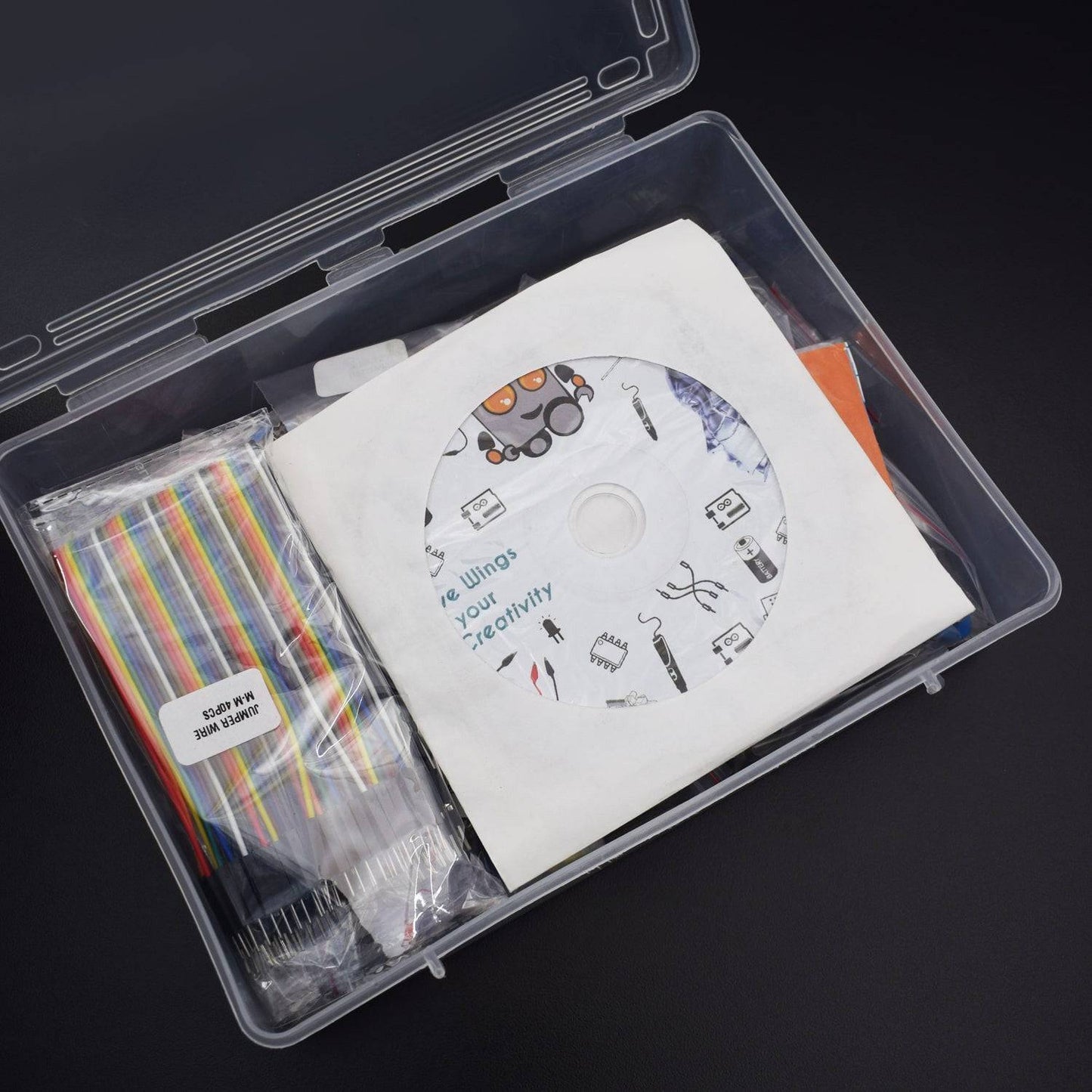
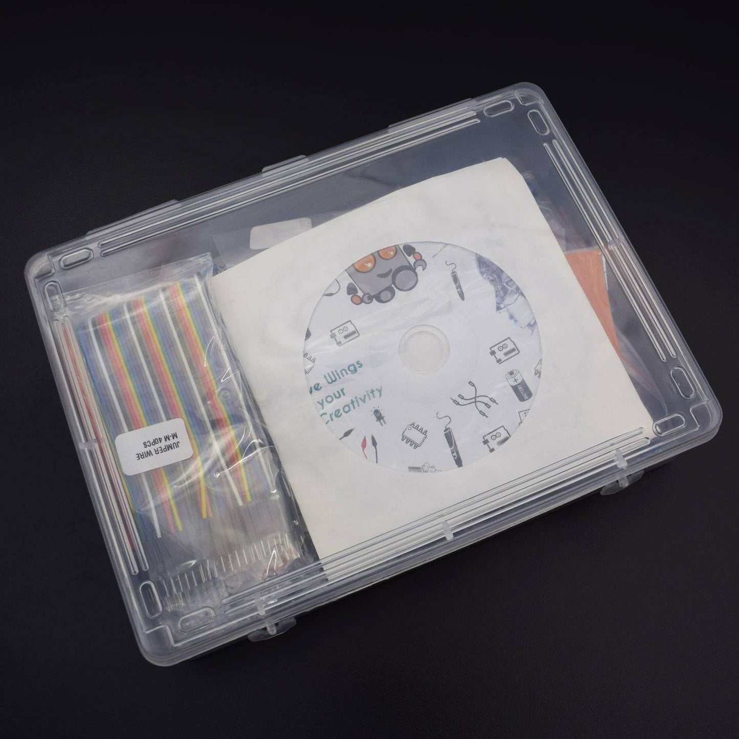
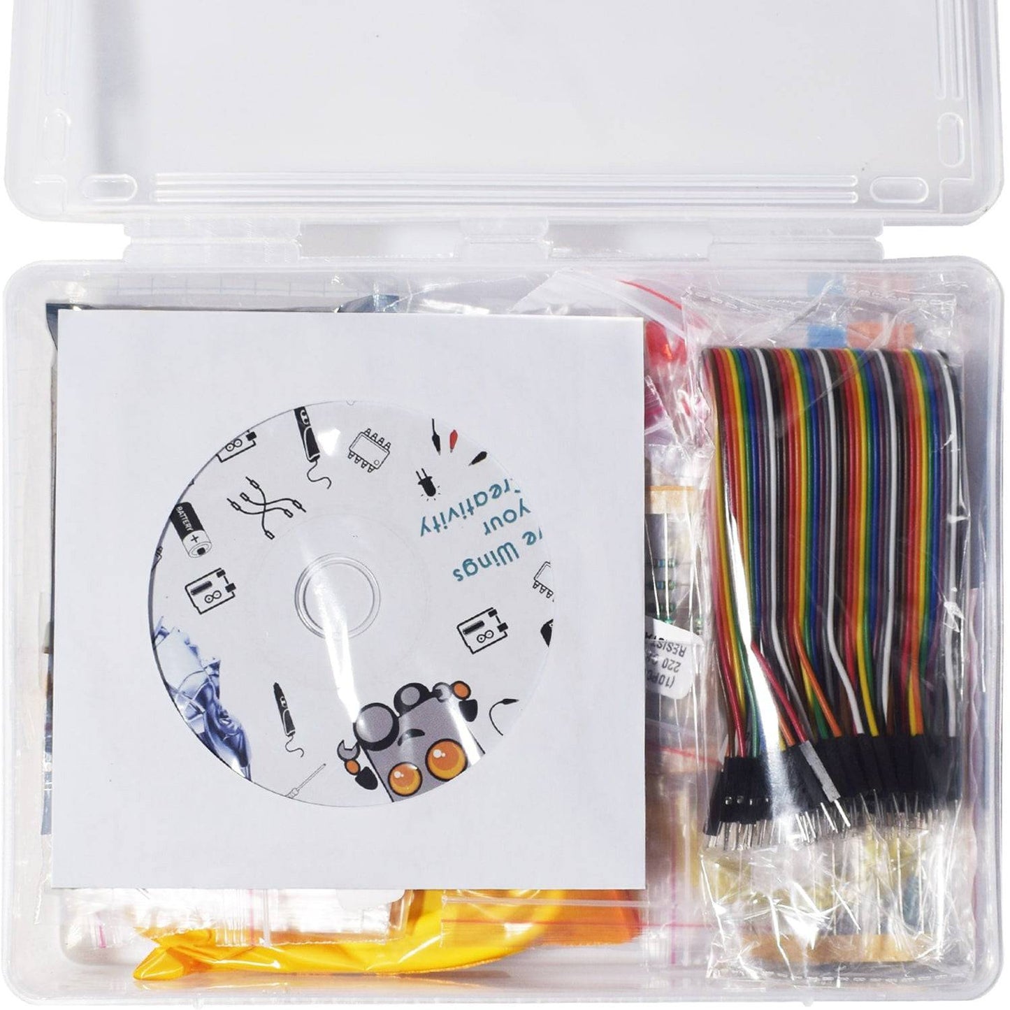
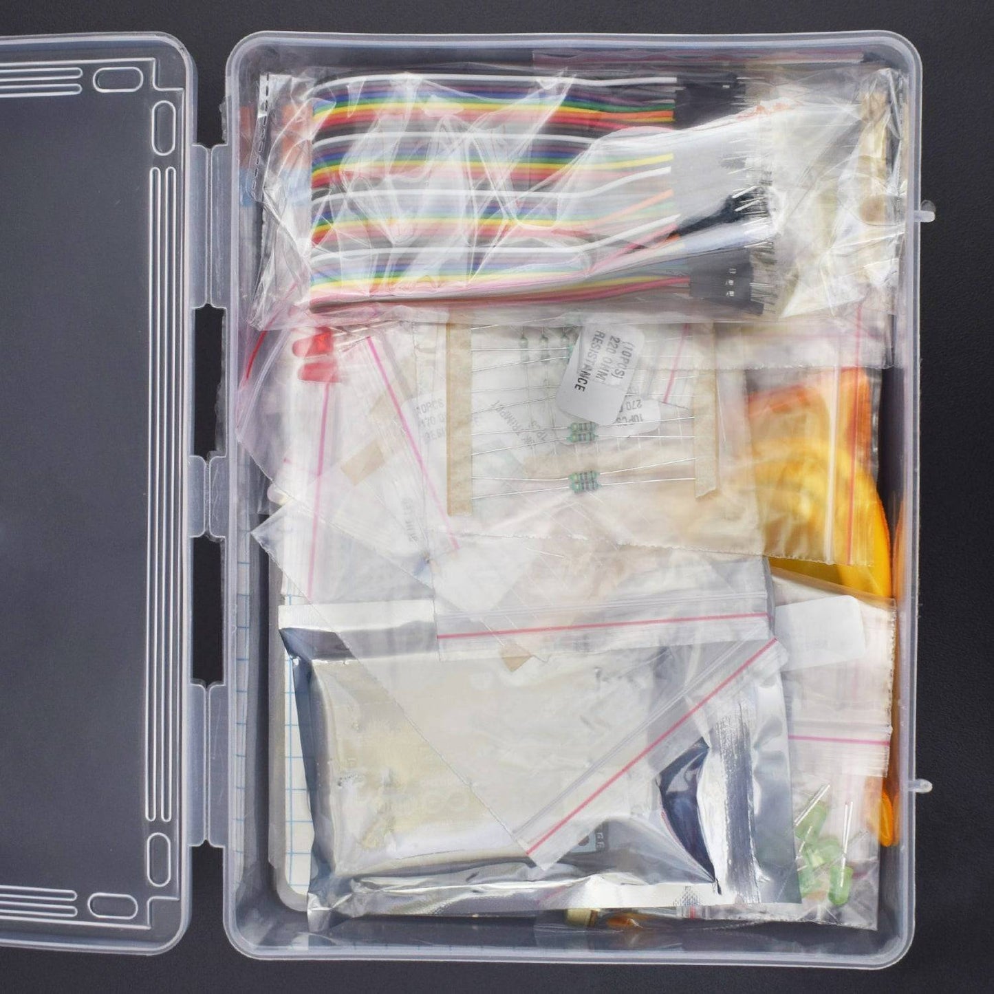
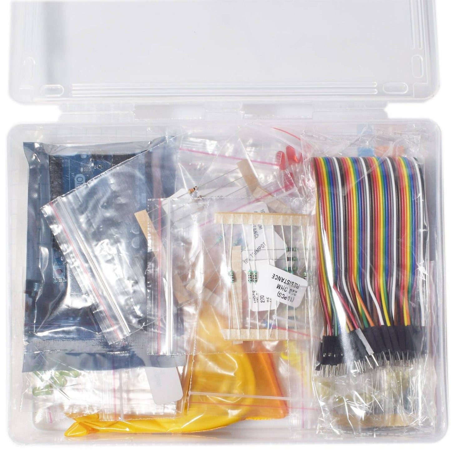
This is the Basic Component kit for School Kids. They can make various project using this component kit. This kit includes Various types of Resistors, Capacitors & Led etc.
Check out the Playlist :
https://www.youtube.com/watch?v=461FVSn15OQ&list=PLeZjSVeikamNuNH8pT5JPKDfhOWMcQaEM

PACKAGE INCLUDED
| Product name | Qty |
| Arduino uno with USB Cable | 2 |
| B-10 Buzzer (Passive) | 1 |
|
Capacitor Electrolytic(47uf (50v) - 1 , 4.7uf (50v)- 1) & 100 uf (50v)- 1) |
|
| Resistor (10k , 1k , 330R , 220R , 470R , 270R ) | 10 pcs each |
| Breadboard 830 pt | 1 |
| Single Stand Wire 1mt | 1 |
| 3mm LDR | 2 |
| RGB led | 1 |
| Jumper wire (male to Male) - 65 pcs & Male to female jumper wires - 10pcs | |
| SN74HC595N Shift Register IC | 1 |
| 5 mm Led (each colour) | 5 pcs each |
| Arduino Case | 1 |
| Push-button | 5 |
| 10K potentiometer (metal) | 1 |
| 10K Pot | 1 |
NOTE –
- Breadboard used in projects are different in size, you will get 830 pt. breadboard
- 9v Battery with snapper used for external power supply which is not included in the kit
- You can add any color of led in the project which has different voltage drop so we have added different resistors.
PROJECT LIST
PRODUCT DESCRIPTION
ARDUINO UNO

LED

LDR

This is a special type of resistor which has no polarity. It can detect the amount of light falling on it
BUZZER

Pin No. |
Pin Name |
Description |
1 |
Positive |
Identified by (+) symbol or longer terminal lead. Can be powered by 6V DC |
2 |
Negative |
Identified by short terminal lead. Typically connected to the ground of the circuit |
PUSH BUTTON

10K POTENTIOMETER

RGB LED

74HC595 SHIFT REGISTER IC

- Wide Supply Voltage Range from 2.0V to 6.0V
- Sinks or sources 8mA at VCC = 4.5V
- CMOS low power consumption
- Schmitt Trigger Action at All Inputs
- Inputs accept up to 6.0V
- ESD Protection Tested per JESD 22
PROJECT- 1
Blink led
In this project, we are going to connect an LED to one of the digital pins rather than using LED13, which is soldered to the board.

Hardware Required
- Red M5 LED - 1
- 220Ω resistor - 1
- Breadboard 830 Points - 1
- Jumper wires (Male to Male) – 10 pcs
- Arduino Uno with USB Cable - 1
Circuit Description

Connect the Components according to the given
- Connect positive leg of LED with Digital Pin 12 of Arduino Uno via 220-ohm resistor to avoid high current damaging the LED.
- Connect the negative leg of LED with GND of Arduino Uno.
Code & Output
Click here to see the code or copy the link:
After downloading this program, in the experiment, you will see the LED connected to pin 12 turning on and off, with an interval approximately one second.
PROJECT- 2
PWM (Pulse Width Modulation)
PWM (Pulse Width Modulation) is a process used to encode analog signal level into digital ones. The voltage or current is fed to analog load (the device that uses power) by repeated pulse sequence being ON or OFF.

PWM has many applications: lamp brightness regulating, motor speed regulating, sound making, etc. The following are the three basic parameters of PWM


Hardware Required
- 10K Potentiometer - 1
- Red M5 LED - 1
- 220Ω resistor - 1
- Breadboard 830 points - 1
- Jumper wires (Male to Male) - 10 pcs
- Arduino Uno with USB Cable – 1
Circuit Description

- First, attach the LED on the Breadboard.
- Connect GND of Arduino with Breadboard to make further GND connections.Connect the positive terminal of LED with the Digital Pin 6 of the Arduino Uno.
- Connect the negative terminal of LED with the GND rail of the Breadboard via 220Ω resistor.
- Then, attach the 10K Potentiometer on the Breadboard.
- Connect the VCC of the Potentiometer with the 5V pin of the Arduino Uno.
- Connect GND of Potentiometer with GND rail of the Breadboard.
- Connect Signal Pin of the Potentiometer with the Analog Pin A1 of the Arduino Uno.
Code & Output
Click to see the code

Welcome to the Arduino Based project in which we have used the analogWrite (PWM interface, analog value) function. In this project, we will read the analog value of the potentiometer and assign the value to PWM port, so there will be corresponding change to the brightness of the LED. One final part will be displaying the analog value on the screen. You can consider this as the "analog value reading" project adding the PWM analog value assigning part. After downloading the program, when we rotate the potentiometer knob, we can see changes of the displaying value, also obvious change of the LED brightness on the breadboard.
PROJECT- 3
Traffic Light
In this project, we will make traffic lights using 3 LEDs with a different color other than 1 LED and make them work accordingly.

Hardware Required
- Breadboard 830 points - 1
- Arduino Uno with USB Cable – 1
- Single stand wire 2mt – 1
- M5 LED (Red, Yellow, Green) – 1 pc each
- 220Ω resistor – 3
- Jumper wires (Male to Male) – 40 pcs
Circuit Description

Connect the Components according to the given diagram above.
- Attach the three LEDs on the Breadboard.
- Connect GND of Arduino with the Breadboard for further GND
- Connect negative terminals of LEDs with the GND rail of the Breadboard via 220Ω resistor.
- Connect the positive terminal of Red LED with the Digital Pin 10 of the Arduino Uno.
- Connect the positive terminal of Yellow LED with the Digital Pin 9 of the Arduino Uno.
- Connect the positive terminal of Green LED with the Digital Pin 8 of the Arduino Uno.
Code & Output
Click to see the code
Welcome to the Arduino Based Project which consists of the LEDs for making a simulation of traffic lights, the blinking time of each LED should be the same with those in the traffic lights system. In the program, we use Arduino delay () function to control delay time.
So, when the uploading process is completed, we can see the traffic lights of our own design.
The green light will be on for 5 seconds, and then off., followed by the yellow light blinking for 3 times, and then the red light on for 5 seconds, forming a cycle. And the cycle repeats.
PROJECT- 4
Led Chasing Effect
We often see billboards composed of colorful LEDs. They are constantly changing to form various effects. In this Project, we compile a program to simulate chase effect.

Hardware Required
- Jumper wires (Male to Male) – 40 pcs
- Any colour 5mm LED – 6
- 220Ω resistor – 6
- Arduino Uno with USB Cable – 1
- Breadboard 830 points – 1
- 9V Battery – 1 (Not included in Kit)
- Snapper with DC Jack – 1
Circuit Description

Connect the Components according to the given diagram
- Attach the six LEDs on the Breadboard.
- Connect the GND of Arduino Uno with the Breadboard to make further GND connections
- Connect negative terminals of all the LEDs with the GND rail of the Breadboard via 220Ω resistor.
- Connect the positive terminals of all the LED with Arduino Uno as follows:
LEDArduino Uno
- LED 1 -> Digital Pin 2
- LED 2 -> Digital Pin 3
- LED 3 -> Digital Pin 4
- LED 4 -> Digital Pin 5
- LED 5 -> Digital Pin 6
- LED 6 -> Digital Pin 7
Code & Output
Click to see the code
Welcome to the Arduino Based LED Chasing Effect Project. In this particular project, the LED’s blink by the sequence in a series pattern.
PROJECT- 5
Button Controlled Led
In this experiment, we will try to use the input function, which is to read the output value of the device connecting to it. We use 1 button and 1 LED using both input and output for the I/O function. When it's pressed, the circuit is in closed (conducting) state.

Hardware Required
- Arduino Uno with USB Cable - 1
- Tactile switch - 1
- LED - 1
- 220Ω resistor – 1
- 10 KΩ resistor - 1
- Breadboard 830 Points – 1
- Jumper wires (Male to Male) – 40 pcs
- 9V Battery – 1 (Not included in Kit)
- Snapper with DC Jack – 1
Circuit Description

Connect the Components according to the given diagram
- Attach the Push Button and LED on the Breadboard.
- Connect the Pin 5V of the Arduino Uno with the Breadboard for further 5V power supply connections.
- Connect GND of the Arduino Uno with the Breadboard for further GND connections.
- Connect the first leg of Push Button with 5V rail of Breadboard.
- Connect 10KΩ resistor on the second leg of the Push Button.
- Connect Digital Pin 7 of Arduino Uno with the second leg of Push Button via 10KΩ resistor (one leg).
- Connect the other leg of the resistor with GND rail of the Breadboard.
- Connect the positive terminal of LED with Digital Pin 11 of Arduino Uno.
- Connect the negative terminal of LED with the GND rail of Breadboard via 220Ω resistor.
Code & Output
Click to see the code
Welcome to the Arduino Based Project which consists of Push Button and leds. When the button is pressed, the LED will be on. In this program, we add a statement of judgment. Here, we have used if () statement. When we press the button, pin 7 will output high level.
We can program pin 11 to output high level and turn on the LED. When pin 7 outputs low level, pin 11 also outputs low level and the LED remains off. When the button is pressed, LED is on, otherwise, LED remains off. After the above process, the button controlled LED experiment is completed. The simple principle of this experiment is widely used in a variety of circuit and electric appliances. You can easily come across it in your everyday life. One typical example is when you press a certain key of your phone, the backlight will be on.
PROJECT- 6
Passive Buzzer
The buzzer we introduced here is a passive buzzer. It cannot be actuated by itself, but by external pulse frequencies. Different frequencies produce different sounds.

Hardware Required
- Breadboard 830 points - 1
- Passive buzzer - 1
- Arduino Uno with USB Cable - 1
- Jumper wires (Male to Male) – 40 pcs
- 9V Battery – 1 (Not included in Kit)
- Snapper with DC Jack – 1
Circuit Description

- First, attach the passive Buzzer on the Breadboard.
- Connect the Digital Pin 8 of Arduino Uno with the positive terminal of the passive Buzzer.
- Connect the GND of Arduino Uno with the negative terminal of the passive Buzzer.
Code & Output
Click to see the code
Welcome to the Arduino Based Project which consists of Passive Buzzer which differs from Active Buzzer in some measures. Its functionality is being described here.
The Passive Buzzer is the slightly shorter one, with the electronics exposed on the bottom. You have to send it an AC "sound signal" via the Arduino. The Arduino needs to generate the "tone". Can create music. It takes processor-time to generate the sound so other processes might slow down. Notice it does not matter which leg you use for positive or negative. The pin can be connected to a passive piezo buzzer or other speaker to play tones.
Only one tone can be generated at a time. If a tone is already playing on a different pin, the call to tone () will have no effect. If the tone is playing on the same pin, the call will set its frequency. After downloading the program, the buzzer experiment is completed.
PROJECT- 7
RGB Led
In this project, we use RGB LED or Tricolour principle to display various colours which are being described here. PWM controlling ports to display full colour.

Hardware Required
- Arduino Uno with USB Cable – 1
- RGB LED – 1
- Jumper wire (Male to Male) – 40 pcs
- 220Ω resistor – 3
- Breadboard 830 points – 1
Circuit Description

Connect the Components according to the given diagram
- Attach RGB LED on the Breadboard. Connect GND of Arduino Uno with Breadboard for making further GND connections.
- Connect the First (Red) Pin of the RGB LED with the Digital Pin 11 of the Arduino Uno via 220Ω resistor.
- Connect GND of RGB LED with Breadboard GND rail.
- Connect the Third (Green) Pin of the RGB LED with the Digital Pin 10 of the Arduino Uno via 220Ω resistor.
- Connect the Third (Blue) Pin of the RGB LED with the Digital Pin 9 of the Arduino Uno via 220Ω resistor.
Code & Output
Click to see the code
Welcome to the Arduino Based RGB LED Project. White light can be produced by mixing different colored lights together
the most common method is to use the primary colors red, green and blue (RGB). As this mechanism involves the blending and diffusion of different colors, this approach is little used for the production of white lighting due to the tendency of it to have a slight tint or hue. Nevertheless, this method is particularly interesting for effect applications because of the flexibility of mixing different colors.
In principle, most perceivable colors can be produced by mixing different amounts of three primary colors, and this makes it possible to produce precise dynamic color control as well. Utilizing the DMX control protocol, it is actually possible to achieve a color palette of over 16 million shades!
Each color scale it is possible to select 256 levels or shades of that color. If you have three primary colors and each one can have 256 different shades, then by mixing them together you can mathematically generate 16.7 million different colors. 255 x 255 x 255 = 16,581,375. RGB LED controllers work on a much simpler principle. They alter the power on each of the three channels (red, green and blue) to create a specific color mix. Directly copy the code into Arduino IDE, and click upload .wait a few seconds, you can see a full-color LED.
PROJECT- 8
Turn On Led using LDR (Photoresistor)
In this project, we will work on Photoresistor (Photovaristor) which includes the photoelectric effect of the semiconductor. Photovaristor is commonly applied in the measurement of light and light control.

Hardware Required
- Arduino Uno with USB Cable - 1
- Breadboard 830 points – 1
- Photoresistor or LDR – 1
- LED - 1
- 10KΩ resistor – 1
- 220Ω resistor – 1
- Jumper wire (Male to Male) – 40 pcs
- 9V Battery – 1 (Not included in the kit)
- Snapper with DC Jack – 1
Circuit Description

Connect the Components according to the given diagram
- Attach LED and LDR on the Breadboard.
- Connect GND of Arduino Uno with Breadboard to make further GND connections.
- Connect 5V Pin of Arduino Uno with Breadboard for further 5V power supply connections.
- Connect the positive terminal of LED with the Digital Pin 11 of the Arduino Uno.
- Connect the negative terminal of LED with the GND rail of Breadboard via 220Ω resistor.
- Connect the one leg of LDR with the 5V power supply rail of Breadboard via 10KΩ resistor on one end and connect another end with the Analog Pin A0 of Arduino Uno.
- Connect another leg of the LDR with the GND rail of Breadboard.
Code & Output
Click to see the code
Welcome to the Arduino Based LDR Project which is based on the photoelectric effect of the semiconductor. Its basic working principle is that if the incident light is intense, its resistance reduces; if the incident light is weak, the resistance increases. Photo varistor is commonly applied in the measurement of light, light control and photovoltaic conversion (convert the change of light into the change of electricity). Photo varistor is an element that changes its resistance as light strength changes. So we will need to read the analog values. We can refer to the PWM experiment, replacing the potentiometer with photo varistor. When there is a change in light strength, there will be corresponding change on the LED. After the connection, let's begin the program compilation process. The program is similar to the one of PWM. After downloading the program, you can change the light strength around the photo varistor and see corresponding brightness change of the LED. Photo varistors have various applications in our everyday life. You can make other interesting interactive projects base on this one.
PROJECT- 9
Analog Value Reading
This project is for learning of analog I/O interfaces. On an Arduino, there are 6 analog interfaces numbered from 0 to 5 and can also be used as digital ones numbered as 14-19.

Hardware Required
- Arduino Uno with USB Cable – 1
- Jumper wire (Male to Male) – 40 pcs
- Breadboard 830 points – 1
- 10K Potentiometer – 1
- LED – 1
- 9V Battery – 1 (Not included in Kit)
- Snapper with DC Jack – 1
Circuit Description

- Attach 10K Potentiometer on the Breadboard.
- Connect GND of Arduino Uno with GND of Potentiometer.
- Connect Pin 5V of Arduino Uno with VCC of Potentiometer.
- Connect Pin Signal of Potentiometer with the Analog Pin A0 of Arduino Uno.
- Connect the positive terminal of LED with Digital Pin 13 of Arduino Uno.
- Connect the negative terminal of LED with GND of Arduino Uno.
Code & Output
Click to see the code
Welcome to the Arduino Based Project which consists of 10K Potentiometer. Here, we will convert the resistance value of the potentiometer to analog ones and display it on the screen. We use the analog interface 0. The A/D acquisition of Arduino 328 is in 10 bits, so the value it reads is among 0 to 1023.
First, we need to set the baud rate in void setup (). Displaying the value is communication between Arduino and PC, so the baud rate of the Arduino should match the one in the PC's software set up. Otherwise, the display will be messy codes or no display at all. In the lower right corner of Arduino software monitor window, there is a button for baud rate set up. The set up here needs to match one in the program. The statement in the program is Serial.begin(); enclosed is the baud rate value, followed by statement for displaying. You can use Serial.print() or Serial.println () statement. The sample program uses built-in LED connected to pin 13. Each time the device reads a value, LED blinks.
When you rotate potentiometer knob, you can see displayed value changes. The reading of analog value is a very common function since most sensors output analog value.

PROJECT- 10
Led pattern using HC595 Shift register IC
74HC595 is a combination of 8-digit shifting register, memorizer and equipped with tri-state output. We will use it to control 8 LEDs. It takes 8 I/O for an Arduino to control 8 LEDs. So, to save port resources, we use 74HC595 to reduce no. of ports it needs.

Hardware Required
- Arduino Uno with USB Cable – 1
- Breadboard 830 points – 1
- Blue LED – 4
- White LED – 4
- Jumper wire (Male to Male) – 40 pcs
- 220Ω resistors – 8
- SN74HC595N IC Shift Register – 1
- 9V Battery – 1 (Not included in Kit)
- Snapper with DC Jack - 1
Circuit Description

Connect the Components according to the given diagram
- Attach the 74HC595 on the Breadboard.
- Attach 8 LEDs with the Breadboard.
- Connect the GND of Arduino Uno with Breadboard for further GND connections.
- Connect Pin 5V of Arduino with Breadboard for further 5V power supply connections
- Connect negative terminals of LEDs with GND rail of Breadboard via 220Ω resistor.
- Connect the positive terminal of LED 1 with Pin Q7 of 74HC595 via Breadboard.
- Connect the positive terminal of LED 2 with Pin Q6 of 74HC595 via Breadboard.
- Connect the positive terminal of LED 3 with Pin Q5 of 74HC595 via Breadboard.
- Connect the positive terminal of LED 4 with Pin Q4 of 74HC595 via Breadboard extended circuit.
- Connect the positive terminal of LED 5 with Pin Q3 of 74HC595 via Breadboard extended circuit.
- Connect the positive terminal of LED 6 with Pin Q2 of 74HC595 via Breadboard extended circuit.
- Connect the positive terminal of LED 7 with Pin Q1 of 74HC595 via Breadboard extended circuit.
- Connect the positive terminal of LED 8 with Pin Q0 of 74HC595 via Breadboard extended circuit.
- Connect VCC of 74HC595 with 5V power supply rail of Breadboard.
- Connect Pin DS (DATA) of 74HC595 with Digital Pin 2 of Arduino Uno.
- Connect Pin ST_CP (RCLK) of 74HC595 with Digital Pin 4 of Arduino Uno.
- Connect Pin SH_CP (SRCLK) of 74HC595 with Digital Pin 5 of Arduino Uno.
- Connect Pin MR (SRCLR) of 74HC595 with 5V rail of Breadboard.
Code & Output
Click to see the code
Welcome to the Arduino Based Project which consists of 74HC595. Here, it is used to save the use of ports given in the Arduino Uno. It is 8-bit serial-in, serial or parallel-out shift register with output latches; 3-state.
You can use it to control 8 outputs at a time while only taking up a few pins on your microcontroller.
PROJECT- 11
Turn On/Off LEDs alternatively using 2 LDR
In this particular project, we will turn LED ON/OFF using LDR when light falls on 1st LDR, the led will turn on for LDR 1 and if we fall the light on 2nd LDR, the second led will turn off.

Hardware Required
- Arduino Uno with USB Cable – 1
- Breadboard 830 points – 1
- LED – 1
- LDR – 1
- 10KΩ resistor – 2
- Jumper wire (Male to Male) – 40 pcs
- Single stand wire 1mt – 1
- 9V Battery – 1 (Not included in Kit)
- Snapper with DC Jack - 1
Circuit Description

Connect the Components according to the given diagram
- Attach the two LDR and LED on the Breadboard.
- Connect GND of Arduino Uno with Breadboard for further GND connections.
- Connect Pin 3.3V of the Arduino Uno with Breadboard for further 3.3V power supply connections.
- Connect one terminal of both LDR 1 and LDR 2 with GND rail of Breadboard.
- Connect both the negative terminal of LEDs with GND rail.
- Connect the positive terminal of LED1 with Pin 13 of Arduino Uno.
- Connect another terminal of LDR1 with Analog Pin A0 with one end of 10KΩ resistor & connect another end of 10KΩ resistor with 3.3V power supply rail of Breadboard as shown in the image below.
- Connect another terminal of LDR 1 with Analog Pin A1 with one end of 10KΩ resistor and connect another end of 10KΩ resistor with 3.3V power supply rail of Breadboard as shown in the image below.
- Connect the positive terminal of LED 2 with Digital Pin 11 of Arduino Uno.
Code & Output
Click to see the code
Welcome to the Arduino Based Project which consists of LDR and LEDs. Here, LDR is used to turn LED ON/OFF. In this project, LDR is being used as a switch. Each time you cover the photocell, the LED (or whatever) is turned on (if it's off) or off (if it's on).
The main functionality of the circuit is being described below. When the Light is given on photocell of LDR 1, then LED 1 turns ON. And when Light is being given on photocell of LDR 2, then LED 2 turns OFF. Following are the outputs of both the LDR’s.
OUTPUT 1

OUTPUT 2

OUTPUT-3

PROJECT- 12
Control the speed of led pattern using10K Potentiometer
In this Led Chaser Project, we will control the speed of LEDs using 10K potentiometer so you can drive multiple LEDs at once.
.jpg)
Hardware Required
- LED (RED & BLUE) – 5 pieces each
- Arduino Unowith USB cable - 1
- Resistor 220 ohm– 10 pcs
- Potentiometer 10 k – 1
- Breadboard 400 points - 1
- Jumper wires (male to male) – 40 pieces
- Mini breadboard 170 points – 1
- 9v battery with DC jack – 1
Circuit Description

Connect the Components according to the given diagram
- Connect all the LEDs on the breadboard.
- LEDs (+) leg from left side of breadboard are connected to the Arduino digital pin number (0,1,2,3,4,5,6,7) via 220-ohm resistor.
- Led's (-) leg are connected to the ground.
- Potentiometer’s 1st leg is connected to the Arduino’s 5v pin.
- Potentiometer’s 2nd leg is connected to the Arduino’s pin no analog pin A0.
- Potentiometer’s 3rd leg is connected to the Arduino’s GND.
- Arduino’s GND pin connected to the resistor GND
Code & Output
Click to see the code or copy the link:
https://drive.google.com/file/d/1Q4A31wkM-udisyy1hCgyG9Mw696NnEE0/view?usp=sharing
In an LED code, we took 1000 ms as the delay between HIGH & LOW, means an LED remains 1 second HIGH & 1 second LOW. In this example, Arduino takes the voltage form the center leg of pot & converts it to digital form (0 - 5 to 0 - 1023). So, when we rotate the nob of the pot to 0V, we are actually decreasing the time between HIGH & LOW & when we rotate the nob of the pot to 5V, we are actually increasing the time between HIGH & LOW. A simple but effective way to control the blinking speed of an LED.
After uploading the code. Unplug the Arduino cable and connect 9v battery power supply.
Here we control the speed of led using the 10k potentiometer. In this circuit we using 8 led to control over the potentiometer that we rotate the knob of a potentiometer from positive to negative that speed variation in the rail of led.
PROJECT- 13
Control an RGB led colour using push buttons to change colour
In this tutorial, we will change the colour of RGB led using push button. On every pressed button we will see the new colour.

Hardware Required
- Arduino Uno with USB cable – 1
- Breadboard 840 points – 1
- Push-button – 3
- RGB led – 1
- Single stand wire 2m - 1
- Jumper wire male to male – 40 pieces
- Resistor 270 ohm -3
Circuit Description

Connect the Components according to the given diagram
- First You Need Three Push Button Fixed on Bread Board Now Pin No 2 Of Push Button All Are Gnd And Pin 3of Push Button Are Connected to Arduino Uno Pin No 5,6,7
- Push Button 1, 2, 3 Now All Push Button Connected to Arduino Uno.
- Make Gnd Rail on Bread Board to Connect to Common Gnd To Circuit.
- Now We Connect the RGB Led, First Put 270 Ohm Resistance In Between Arduino Connection A Led Shown Given Above in Circuit Diagram Led Pin No 2 Is Connect to Gnd, And Pin No 1 Connect to Arduino Pin No 11.
- Pin 3 Connect To Arduino Pin No 10.
- Pin 4 Connect To Arduino Pin No 9.
- Here All The Connections Setup Now Upload The Code.
Code & Output
Click here to see the code or copy the link:
https://drive.google.com/open?id=0BxpdhMRymue7bUFvSmR2X0NPQms
- To start with, all the LEDs will be off. If you press and hold one of the buttons, then the LED will gradually get brighter. The color will be red for the top button, green for the middle one and blue for the bottom button.
- When you have got enough of one color, try pressing another button and see how they mix together.
- If you want to start over, then press the reset button on the Arduino. This is the red button, next to the USB connector.
PROJECT- 14
Blink LEDs in series pattern
In this project, we will light up the 3 LEDs in series pattern as we see on Diwali Festival .

Hardware Required
- Arduino Uno with USB cable - 1
- LED - 3
- Breadboard 400 points - 1
- Single stand Wire 1m - 1
- Jumper wires (male to male) – 40 pieces each
Circuit Description

Connect the Components according to the given diagram
- Connect 3 LEDs on the breadboard
- From left side 1st led’s positive leg connected to Arduino’s pin no 13 and led’s 2nd leg to Ground.
- 2nd led's positive leg connected to Arduino’s pin no 12 and led 2nd leg is GND.
- 3rd led's positive leg connected to Arduino’s pin no 11 and led 2nd leg is GND.
- Connect Arduino’s GND to breadboard GND to make the further negative connection.
- Upload the code given below
Code & Output
Click to see the code or copy the link:
Upload the code and you will see three led’s glow in a series pattern
PROJECT- 15
Make a Capacitance meter
In this project we will make a capacitor meter in which by using Arduino’s digital pin and serial monitor we can measure unknown capacitor’s value.
This is calculation-based technique by charging and discharging capacitor through unknown value resistor and by calculating the time delay. We can measure unknown capacitance value in farad.

Hardware Required
- Arduino Uno with USB Cable – 1
- 400 Pt Breadboard -1
- Male to Male Jumper wires – 10 pcs
- Resistor (220 ohm – 2 & 10K – 2)
- Capacitor (47 µf and 100 µf) – 1pc
Circuit Description

Connect the Components according to the given diagram
- Attach 10 KΩ resistor to the breadboard
- Connect one of the terminals of 10 KΩ resistor to the digital pin 13 of Arduino Uno.
- Connect another terminal of 10 KΩ with a terminal of 220 Ω resistor
- Connect this junction point to the analog pin A0 of Arduino Uno
- Another terminal of 220 Ω resistor to the Digital pin 11 of Uno.
- Connect positive pin of any Electrolyte capacitor to the junction point of 10 KΩ and 220 Ω resistor.
- Connect GND pin of capacitor to the GND rail on the breadboard.
- Connect GND pin of Arduino Uno to the GND rail on the Breadboard.
NOTE: Here Digital pin 13 used as charge pin for capacitor and digital pin 11 as discharge pin. The time constant output fed into analog pin A0.
Here 220-ohm resistor and wires connected to pin 11 are not necessary but recommended as it speeds up the discharging rate.
Code & Output
Click to see the code
https://drive.google.com/open?id=14AdRa68X4ZKxRrEtV0uKzihjyO2Z92qi
After uploading the code, Open the serial monitor you can see the value of measured capacitance.
The first Value is how long it took the capacitor to reach 63.2 of its total charge. the second value is the calculated capacitance in either in “Nano” or “µf”.
This circuit is most accurate for capacitance value between 1 µf to 3500 µf.
