


vendor-unknown
ARDUIN0 Mega ADK R3 ATmega2560 Compatible Google ADK With USB Cable- NA007-AR040
ARDUIN0 Mega ADK R3 ATmega2560 Compatible Google ADK With USB Cable- NA007-AR040
SKU:NA007-AR040
6374 in stock
Couldn't load pickup availability
- For Bulk Order Click Here
- Need Customer Support?
- Free Delivery Above 999/-
Note: In case you receive a damaged or faulty product, please return it in the original box with all foam and packaging. Returns will not be accepted if further damage occurs due to improper packing.
For refund/return/replacement, call us at +91 95995 94520 or email us at support@rees52.com
Delivery Time
Delivery Time
- Delivery time with the Express Shipping option is 2-3 working days, and with the Standard Shipping option is 5-6 working days. It varies based on location, reliant on courier services.
- Delivery time if the order item is on Preorder Status is 15-20 working days.
COD (Cash on Delivery)
COD (Cash on Delivery)
- For COD you have to pay extra charges of Rs 350/- before the shipment. (We will share the company QR Code, UPI ID or Account details for the same)
- Microcontroller: ATmega2560
- Operating Voltage: 5V
- Input Voltage (Recommended): 7-12V
- Input Voltage (Limits): 6-20V
- Digital I/O Pins: 54 (of which 15 provide PWM output)
Description:
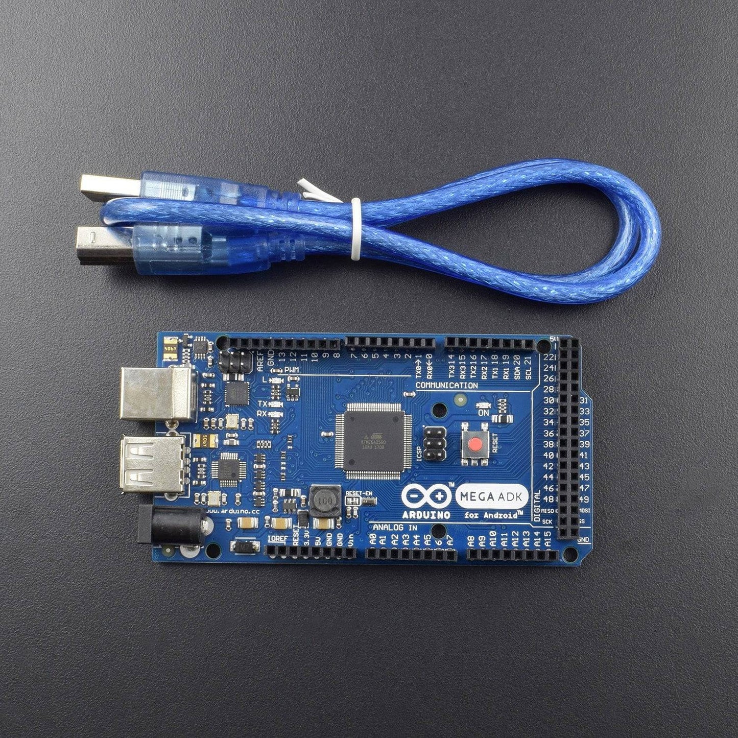
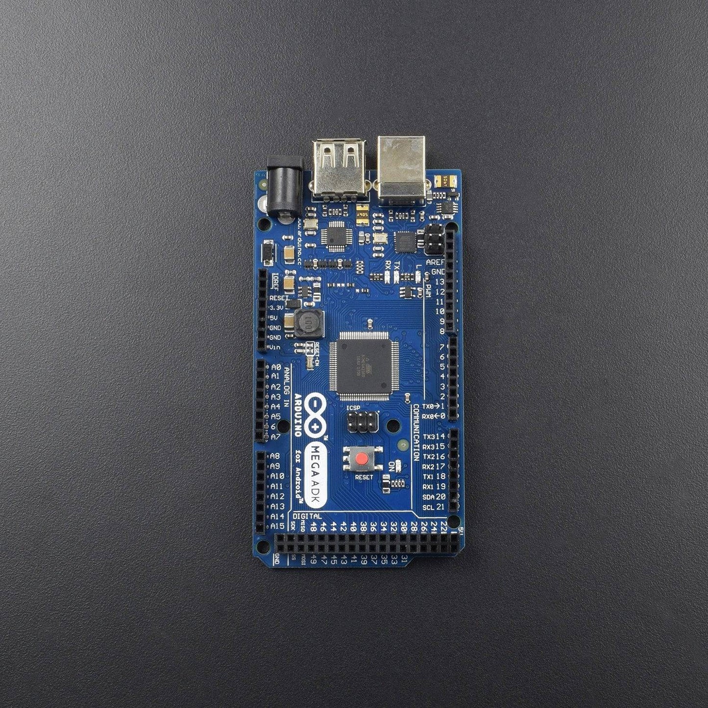
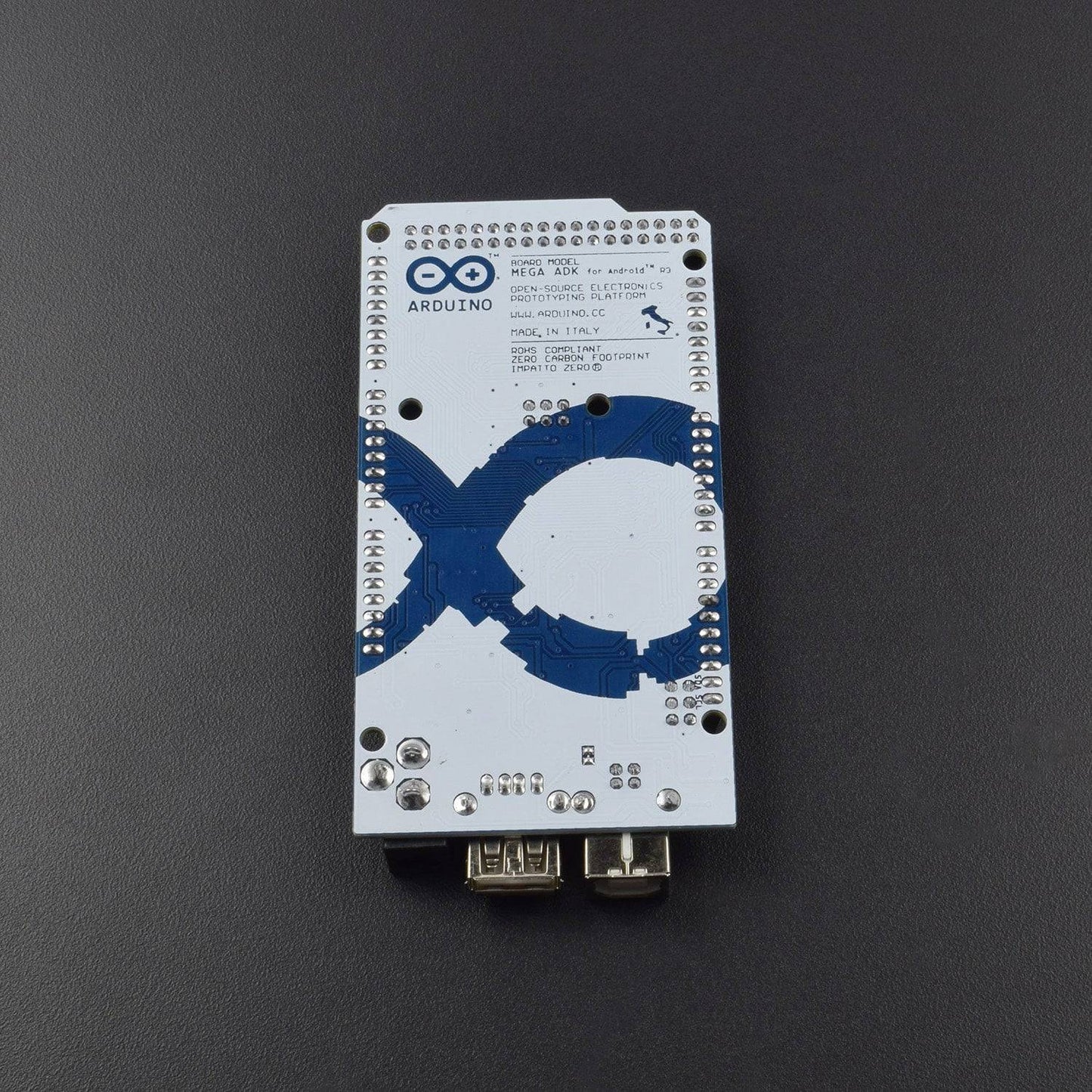
The ARDUIN0 MEGA ADK is a microcontroller board based on the ATmega2560. It has a USB host interface to connect with Android based phones, based on the MAX3421e IC. It has 54 digital input/output pins (of which 15 can be used as PWM outputs), 16 analog inputs, 4 UARTs(hardware serial ports), a 16 MHz crystal oscillator, a USB connection, a power jack, an ICSP header, and a reset button. The MEGA ADK is based on the Mega 2560. Similar to the Mega 2560 and Uno, it features an ATmega8U2 programmed as a USB-to-serial converter. Revision 2 of the Mega ADK board has a resistor pulling the 8U2 HWB line to ground, making it easier to put into DFU mode. Revision 3 of the board has the following new features:
- 1.0 pinout: added SDA and SCL pins that are near to the AREF pin and two other new pins placed near to the RESET pin, the IOREF that allow the shields to adapt to the voltage provided from the board. In future, shields will be compatible both with the board that use the AVR, which operate with 5V and with the ARDUIN0 Due that operates with 3.3V. The second one is a not connected pin, that is reserved for future purposes.
- Stronger RESET circuit.
Specification:
| Microcontroller | ATmega2560 |
| Operating Voltage | 5V |
| Input Voltage (recommended) | 7-12V |
| Input Voltage (limits) | 6-20V |
| Digital I/O Pins | 54 (of which 15 provide PWM output) |
| Analog Input Pins | 16 |
| DC Current per I/O Pin | 40 mA |
| DC Current for 3.3V Pin | 50 mA |
| Flash Memory | 256 KB of which 8 KB used by bootloader |
| SRAM | 8 KB |
| EEPROM | 4 KB |
| Clock Speed | 16 MHz |
| USB Host Chip | MAX3421E |
| Length | 101.52 mm |
| Width | 53.3 mm |
Power:
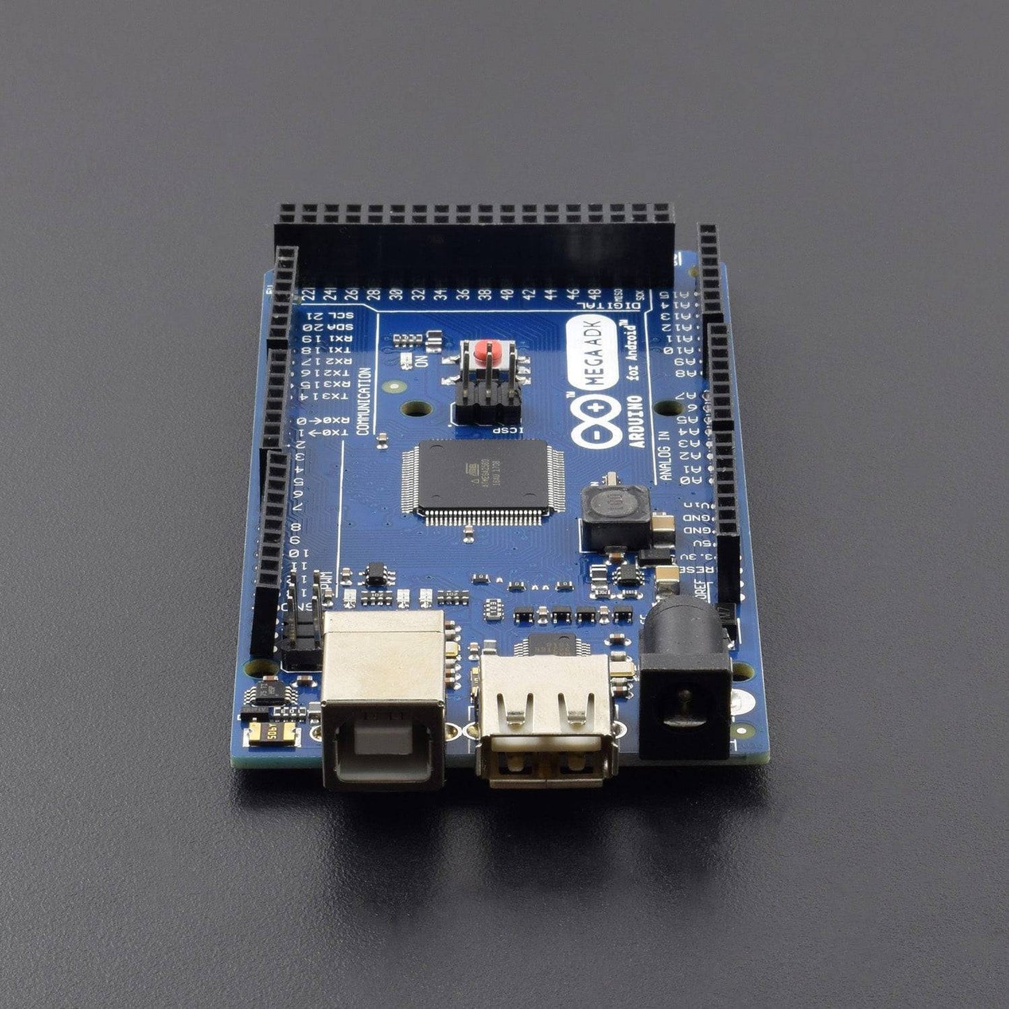
The ARDUIN0 MEGA ADK can be powered via the USB connection or with an external power supply. The power source is selected automatically.
External (non-USB) power can come either from an AC-to-DC adapter (wall-wart) or battery. The adapter can be connected by plugging a 2.1mm center-positive plug into the board's power jack. Leads from a battery can be inserted in the Gnd and Vin pin headers of the POWER connector.
NB: Because the MEGA ADK is a USB Host, the phone will attempt to draw power from it when it needs to charge. When the ADK is powered over USB, 500mA total is available for the phone and board.The external power regulator can supply up to 1500mA. 750mA is available for the phone and MEGA ADK board. An additional 750mA is allocated for any actuators and sensors attached to the board. A power supply must be capable of providing 1.5A to use this much current.
The board can operate on an external supply of 5.5 to 16 volts. If supplied with less than 7V, however, the 5V pin may supply less than five volts and the board may be unstable. If using more than 12V, the voltage regulator may overheat and damage the board. The recommended range is 7 to 12 volts.
The power pins are as follows:
- VIN: The input voltage to the ARDUIN0 board when it's using an external power source (as opposed to 5 volts from the USB connection or other regulated power source). You can supply voltage through this pin, or, if supplying voltage via the power jack, access it through this pin.
- 5V: This pin outputs a regulated 5V from the regulator on the board. The board can be supplied with power either from the DC power jack (7 - 12V), the USB connector (5V), or the VIN pin of the board (7-12V). Supplying voltage via the 5V or 3.3V pins bypasses the regulator, and can damage your board. We don't advise it.
- 3V3: A 3.3 volt supply generated by the on-board regulator. Maximum current draw is 50 mA.
- GND: Ground pins.
- IOREF: This pin on the ARDUIN0 board provides the voltage reference with which the microcontroller operates. A properly configured shield can read the IOREF pin voltage and select the appropriate power source or enable voltage translators on the outputs for working with the 5V or 3.3V.
Memory:
The MEGA ADK has 256 KB of flash memory for storing code (of which 8 KB is used for the bootloader), 8 KB of SRAM and 4 KB of EEPROM (which can be read and written with the EEPROM library).
Input And Output:
Each of the 50 digital pins on the MEGA ADK can be used as an input or output, using pinMode(),digitalWrite(), and digitalRead() functions. They operate at 5 volts. Each pin can provide or receive a maximum of 40 mA and has an internal pull-up resistor (disconnected by default) of 20-50 kOhms. In addition, some pins have specialized functions:
- Serial: 0 (RX) and 1 (TX); Serial 1: 19 (RX) and 18 (TX); Serial 2: 17 (RX) and 16 (TX); Serial 3: 15 (RX) and 14 (TX). Used to receive (RX) and transmit (TX) TTL serial data. Pins 0 and 1 are also connected to the corresponding pins of the ATmega8U2 USB-to-TTL Serial chip.
- External Interrupts: 2 (interrupt 0), 3 (interrupt 1), 18 (interrupt 5), 19 (interrupt 4), 20 (interrupt 3), and 21 (interrupt 2). These pins can be configured to trigger an interrupt on a low value, a rising or falling edge, or a change in value. See the attach Interrupt() function for details.
- PWM: 2 to 13 and 44 to 46. Provide 8-bit PWM output with the analog Write() function.
- SPI: 50 (MISO), 51 (MOSI), 52 (SCK), 53 (SS). These pins support SPI communication using the SPI library. The SPI pins are also broken out on the ICSP header, which is physically compatible with the Uno, Duemilanove and Diecimila.
- USB Host: MAX3421E.
The MAX3421E communicate with ARDUIN0 with the SPI bus. So it uses the following pins:
-
Digital: 7 (RST), 50 (MISO), 51 (MOSI), 52 (SCK).
NB:Please do not use Digital pin 7 as input or output because is used in the communication with MAX3421E - Non broken out on headers: PJ3 (GP_MAX), PJ6 (INT_MAX), PH7 (SS).
- LED: 13.There is a built-in LED connected to digital pin 13. When the pin is HIGH value, the LED is on, when the pin is LOW, it's off.
- TWI: 20 (SDA) and 21 (SCL). Support TWI communication using the Wire library. Note that these pins are not in the same location as the TWI pins on the Duemilanove or Diecimila.
The MEGA ADK has 16 analog inputs, each of which provides 10 bits of resolution (i.e. 1024 different values). By default they measure from ground to 5 volts, though is it possible to change the upper end of their range using the AREF pin and analogReference() function.
There are a couple of other pins on the board:
- AREF: Reference voltage for the analog inputs. Used with analogReference().
- Reset: Bring this line LOW to reset the microcontroller. Typically used to add a reset button to shields which block the one on the board.
Communication:
- The ARDUIN0 MEGA ADK has a number of facilities for communicating with a computer, another Arduino, or other microcontrollers. The ATmega2560 provides four hardware UARTs for TTL (5V) serial communication. An ATmega8U2 on the board channels one of these over USB and provides a virtual com port to software on the computer (Windows machines will need a .inf file, but OSX and Linux machines will recognize the board as a COM port automatically. The Arduino software includes a serial monitor which allows simple textual data to be sent to and from the board. The RX and TX LEDs on the board will flash when data is being transmitted via the ATmega8U2/16U2 chip and USB connection to the computer (but not for serial communication on pins 0 and 1).
- A SoftwareSerial library allows for serial communication on any of the MEGA ADK's digital pins.
- The ATmega2560 also supports TWI and SPI communication. The ARDUIN0 software includes a Wire library to simplify the use of the TWI bus; see the Wire library for details. For SPI communication, use the SPI library.
- The USB host interface given by MAX3421E IC allows the ARDUIN0 MEGA ADK to connect and interact to any type of device that has a USB port. For example, allows you to interact with many types of phones, controlling Canon cameras, interfacing with keyboard, mouse and games controllers as Wiimote and PS3.
Package Included:
- 1 x ARDUIN0 Mega ADK R3 ATmega2560
- 1 x A to B Cable