

vendor-unknown
Access a 4 digit Passcode using joystick module and display the code on 16*2 Lcd interfacing with Arduino uno - KT986
Access a 4 digit Passcode using joystick module and display the code on 16*2 Lcd interfacing with Arduino uno - KT986
SKU:KT986
Low stock: 7 left
Couldn't load pickup availability
- For Bulk Order Click Here
- Need Customer Support?
- Free Delivery Above 999/-
Note: In case you receive a damaged or faulty product, please return it in the original box with all foam and packaging. Returns will not be accepted if further damage occurs due to improper packing.
If you order a product that is currently in Preorder, and the price of that item increases in the future, you will be required to pay the difference in price.
For refund/return/replacement, call us at +91 95995 94520 or email us at support@rees52.com
Delivery Time
Delivery Time
- Delivery time with the Express Shipping option is 2-3 working days, and with the Standard Shipping option is 5-6 working days. It varies based on location, reliant on courier services.
- Delivery time if the order item is on Preorder Status is 15-20 working days.
COD (Cash on Delivery)
COD (Cash on Delivery)
- For COD you have to pay extra charges of Rs 350/- before the shipment. (We will share the company QR Code, UPI ID or Account details for the same)


KIT INCLUDES:
- Arduino Uno with USB cable – 1
- Breadboard 830 points – 1
- Potentiometer 10k – 1
- 16*2 LCD Display – 1
- Joystick module – 1
- Jumper wires male to male – 40 pieces
- Jumper wires male to female – 40 pieces
- Resistor 820 OHM - 5
Introduction
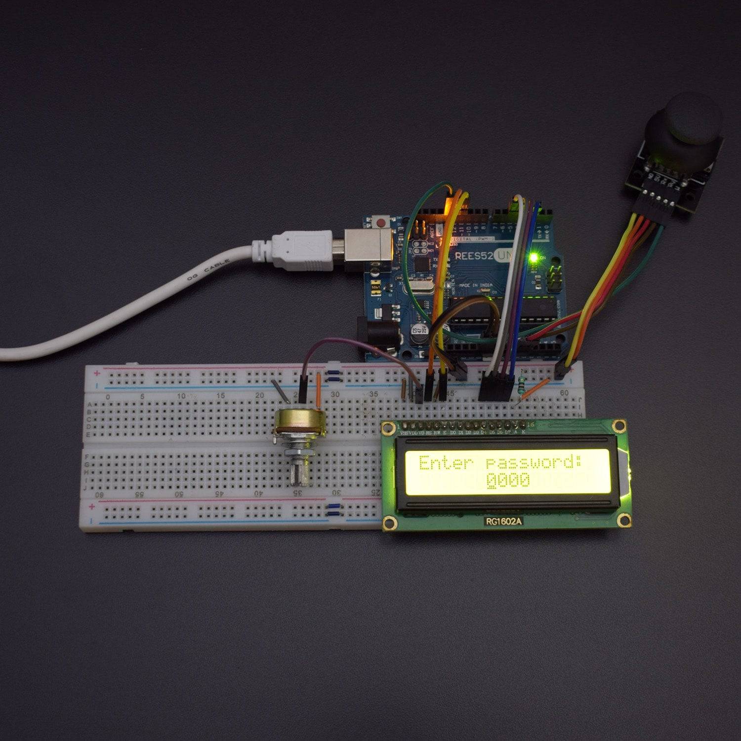
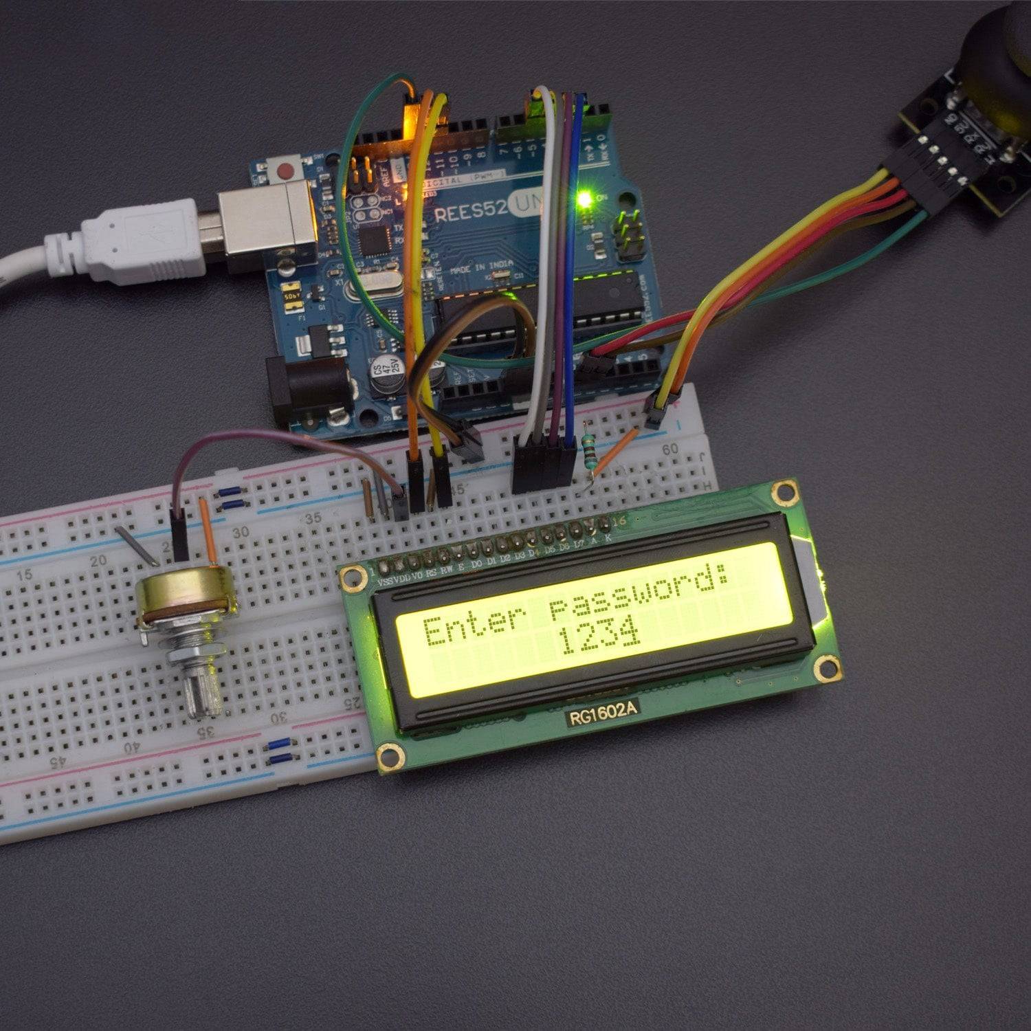
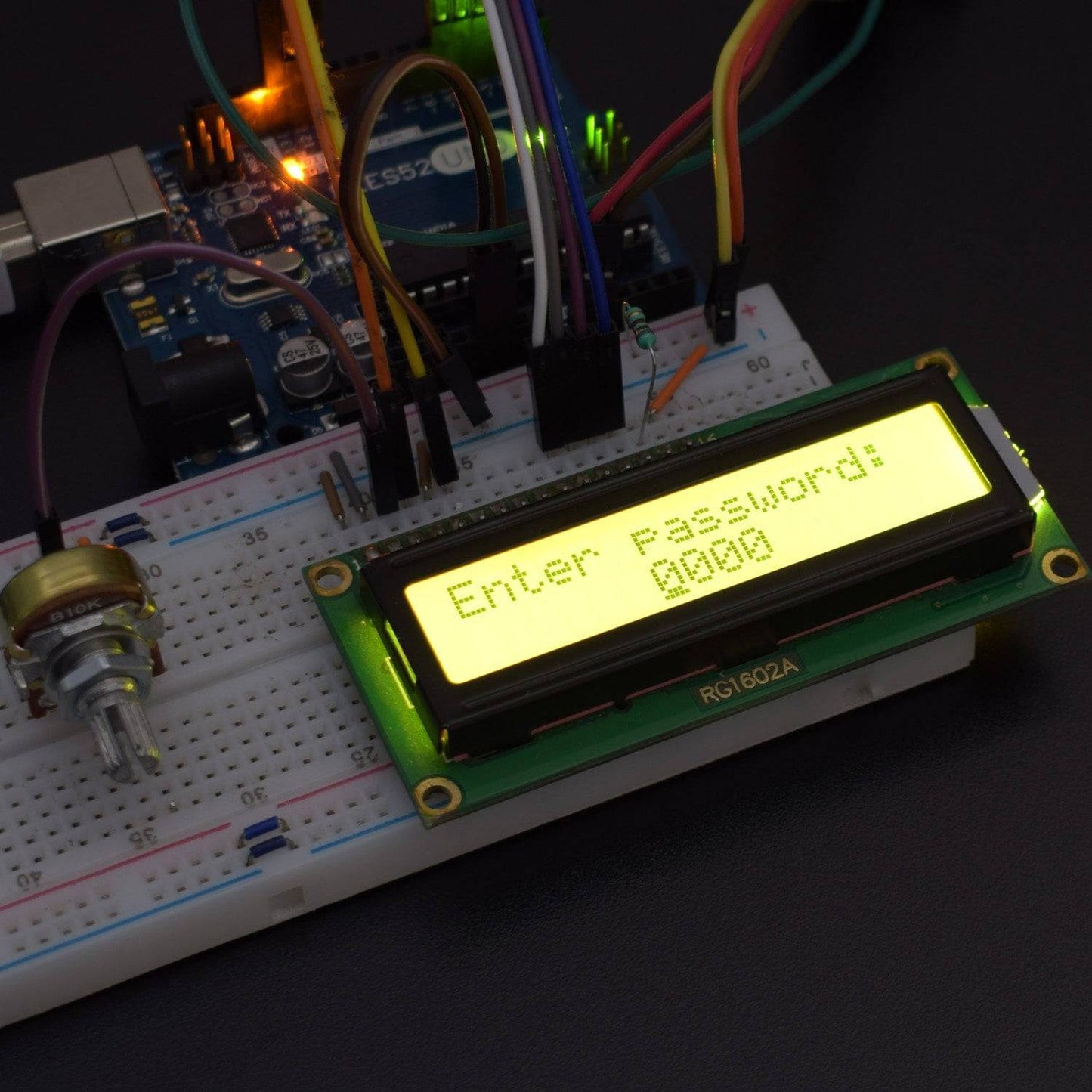
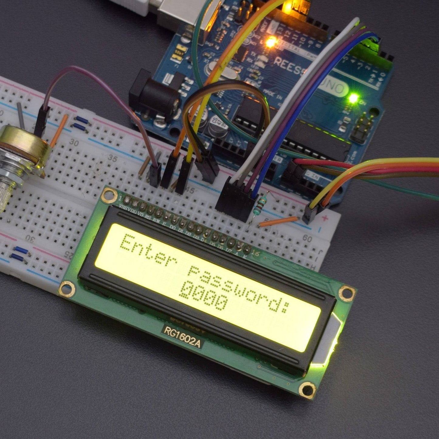
In this project, we will make a 4 digit passcode safe lock using the Ps2 joystick module and 16*2 Lcd display. We will move the joystick in x and y direction to increase or decrease the value from 0 to 9 and other to move the joystick in up and downside to move the cursor in both left and right direction which is displayed on the display.
HARDWARE REQUIRED
- Arduino UNO with USB cable – 1
- Breadboard 830 points – 1
- Potentiometer 10k – 1
- 16*2 LCD Display – 1
- Joystick module – 1
- Jumper wires male to male – 40 pieces
- Jumper wires male to female – 40 pieces
- Resistor 820 OHM - 5
SOFTWARE REQUIRED
Arduino IDE 1.8.5 (programmable platform for Arduino)
Click To Download:https://www.arduino.cc/en/Main/Software


SPECIFICATIONS
Joystick Module
- Supply Voltage: 3.3V to 5V
- Interface: Analog x2,Digital x1
- PH2.0 Interface
- Size:35x39mm
- Weight:15g
16*2 LCD
- Standard 16x2 Character LCD
- 16 Characters Wide x 2 Lines
- 5 x 8 Dots with Cursor
- Built in Controller (HD44780 or equivalent)
- +3.3V Power Supply
- Backlight Included
PIN DESCRIPTION
Joystick module


10k potentiometer


16*2 LCD Display


CIRCUIT DESCRIPTION
NOTE - here we are using a 10k potentiometer but as shown in the figure, the resistor going from 5v and GND to the LCD pin3 V0 replace the 10K potentiometer. You can use 1k ohm from 5v and 330 ohms going down to GND but you may use different resistors or pot depending on the LCD, But for the convenience, we are using 10K pot.


Joystick Module - Arduino Uno
Joystick module has 5 pins gnd, vcc,vrx,vry,sw
NOTE - Here this switch pin on Joystick must be connected to a digital output pin mode. if not then it doesn't give accurate readings so best to use digital pin 13 here.
| Joystick Module | Arduino Uno |
| Vcc | 5v |
| Gnd | Gnd |
| VRx | A1 |
| VRy | A0 |
| SW | 13 |
16*2 LCD Display - Arduino Uno
| 16*2 LCD Dsiplay | Arduino uno |
| VSS | Gnd |
| VDD | 5v |
| V0 | Middle(Data) pin of 10k potentiometer |
| RS | 12 |
| R/W | Gnd |
| E | 11 |
| D4 | 5 |
| D5 | 4 |
| D6 | 3 |
| D7 | 2 |
| A | VCC via 820 ohm |
| K | GND |
CODE
Click to see the code or copy the link
WORKING
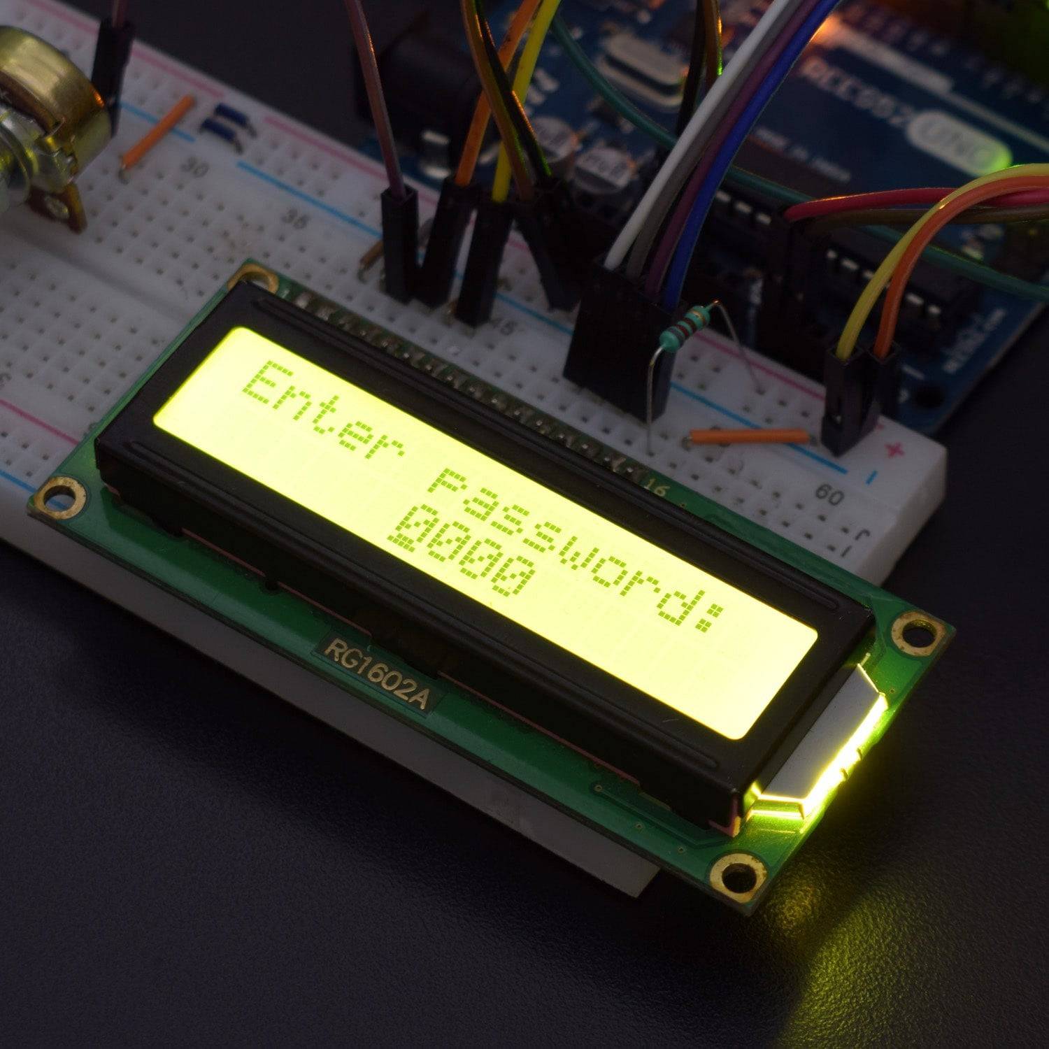
- Plug the supply to Arduino UNO after uploading the code you see the text on display enter the code
- Now you enter the code using the joystick movement left to right to change the cursor position
- Move the joystick Down and up to change the number.
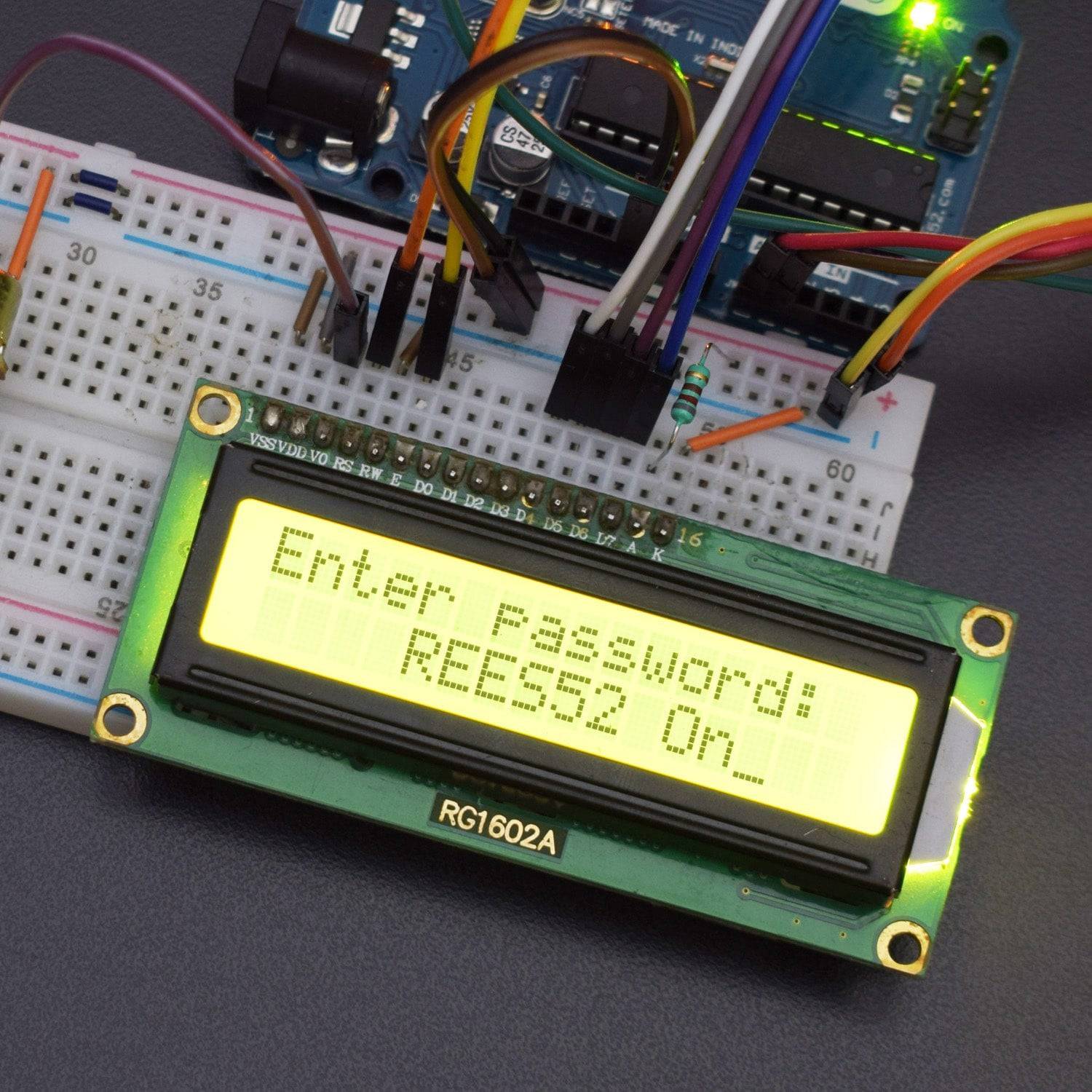
- Now set the number as mentioned in the code (you can change in the code ). Now press joystick after taking in the center position so you can see the REES52 Lock on (You can customize it) password on the LCD display.