


vendor-unknown
4 way IR sensor module interfacing with Arduino uno - KT728
4 way IR sensor module interfacing with Arduino uno - KT728
SKU:KT728
1000 in stock
Couldn't load pickup availability
- For Bulk Order Click Here
- Need Customer Support?
- Free Delivery Above 999/-
Note: In case you receive a damaged or faulty product, please return it in the original box with all foam and packaging. Returns will not be accepted if further damage occurs due to improper packing.
If you order a product that is currently in Preorder, and the price of that item increases in the future, you will be required to pay the difference in price.
For refund/return/replacement, call us at +91 95995 94520 or email us at support@rees52.com
Delivery Time
Delivery Time
- Delivery time with the Express Shipping option is 2-3 working days, and with the Standard Shipping option is 5-6 working days. It varies based on location, reliant on courier services.
- Delivery time if the order item is on Preorder Status is 15-20 working days.
COD (Cash on Delivery)
COD (Cash on Delivery)
- For COD you have to pay extra charges of Rs 350/- before the shipment. (We will share the company QR Code, UPI ID or Account details for the same)
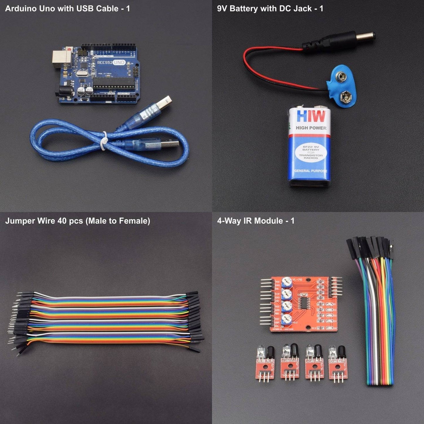
KIT INCLUDES:
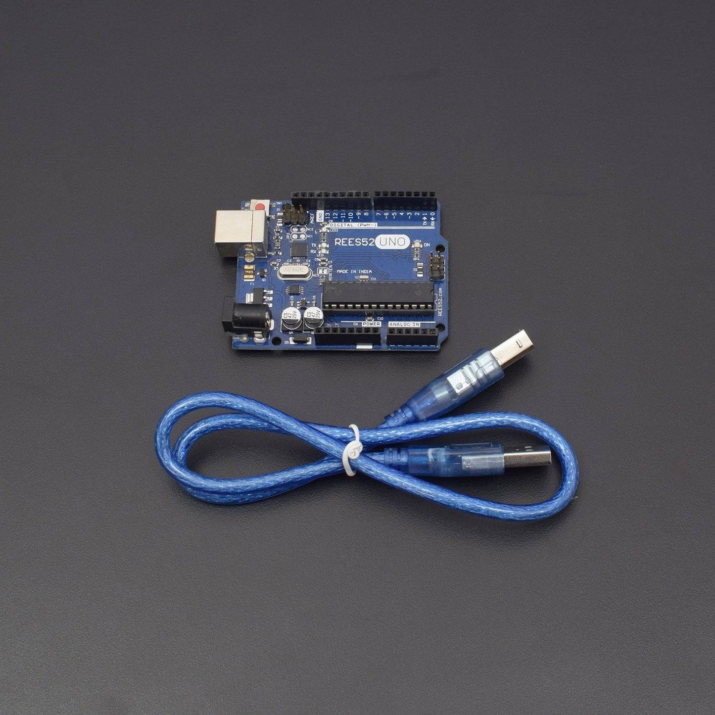
- Arduino uno with USB Cable – 1
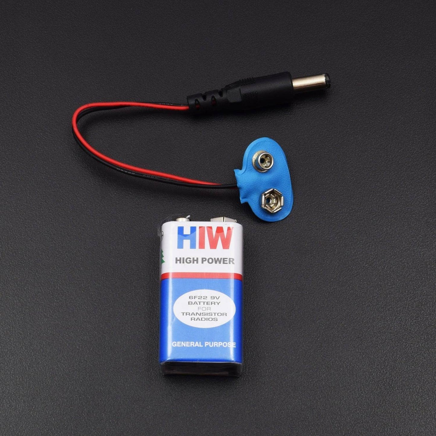
- 9V battery with DC Jack – 1
- Jumper wire male to female – 40 pieces
- Jumper wire male to male – 40 pieces
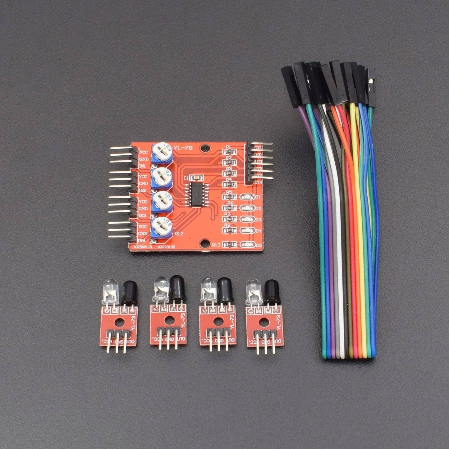
- 4 way IR Module - 1
HARDWARE REQUIRED
- Arduino uno with USB Cable – 1
- 9V battery with DC Jack – 1
- Jumper wire male to female – 40 pieces
- Jumper wire male to male – 40 pieces
- 4 way IR Module - 1
SOFTWARE REQUIRED
Arduino IDE 1.8.5 (programmable platform for Arduino)
Click To Download :https://www.arduino.cc/en/Main/Software

SPECIFICATIONS
4 way IR sensor Module
- Operating voltage: DC 3.3V-5V
- Operating Current:>1A
- Operating temperature: -10 - +50
- Mounting Hole: M3 screws
- Detection distance: 1mm to 60cm adjustable
- Output Interface: 6-wire (1234: signal output, +: positive supply -: ground)
- Output signal: TTL level
The 4-Channel Line Tracker sensor provides an easy way for line tracking. A line sensor is composed of a number cells and each cell is composed of a sender and a receiver. The particularity of this sender/receiver pair is that it sends light that shall be reflected by the line to be detected but not by the eventually opaque background surrounding this line. Any sender/receiver pair that is able to make a difference between a line and the rest of ground (of a different color) can be used in a line sensor.
PIN DESCRIPTION
4 way IR sensor Module
- VCC: 3.3V-5V DC
- GND: ground
- OUT1: high/low output
- OUT2: high/low output
- OUT3: high/low output
- OUT4: high/low output
Sensor Module
a. VCC-VCC
b. GND-GND
c. IN-OUT


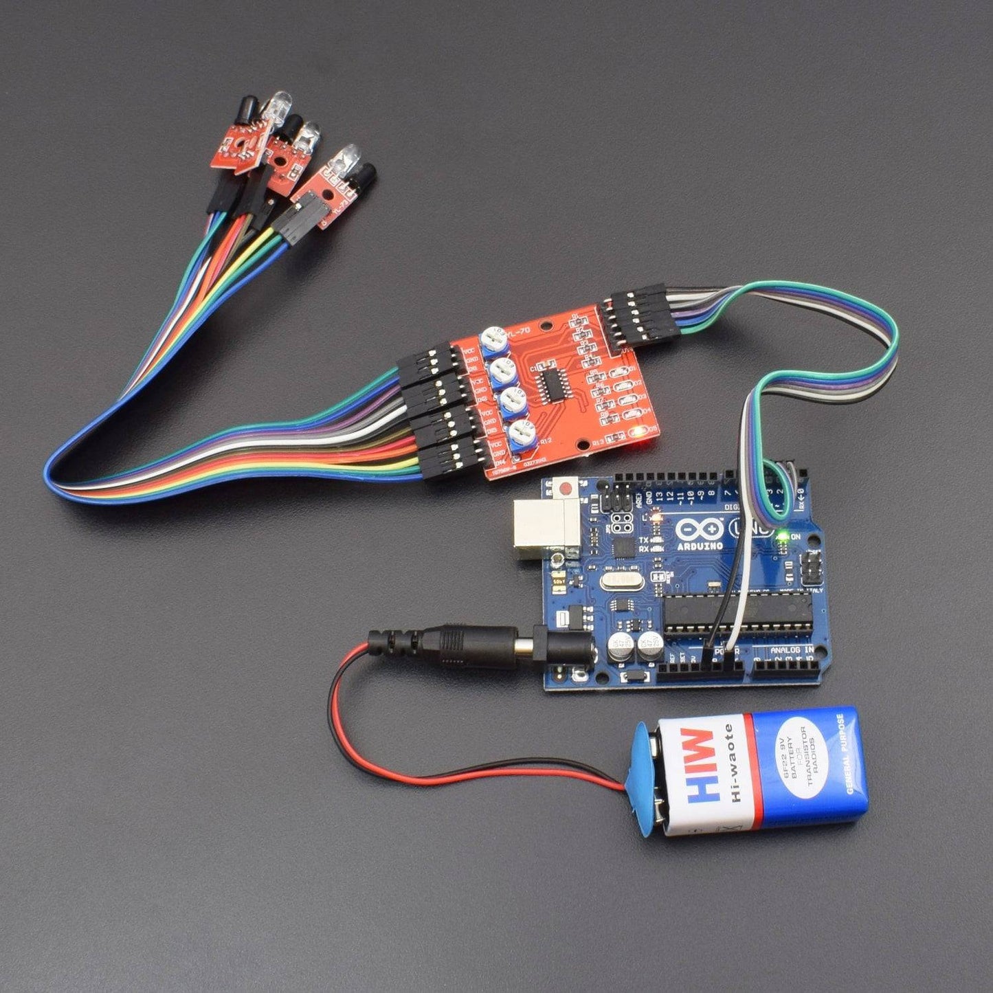
CIRCUIT CONNECTION

The components to be used are:
- microcontroller (any compatible arduino)
- 4-channel line tracker sensor
- Pin connectors
- Breadboard
- USB cable

- Connect the 4-channel sensor module to the control module.
- Connect the components based on the figure shown in the wiring diagram using pin connectors. VCC pin is connected to the 3.3V or 5V power supply, GND pin is connected to the GND, OUT1, OUT2, OUT3, and OUT4 pins are connected to the digital I/O pin. Pin number is based on the actual program code.
- After hardware connection, insert the sample sketch into the Arduino IDE.
- Using a USB cable, connect the ports from the microcontroller to the computer.
- Upload the program.
- See the results in the serial monitor.
CODE
void setup()
{
Serial.begin(9600);
} void loop()
{
Serial.print(digitalRead(2));
Serial.print(" ");
Serial.print(digitalRead(3));
Serial.print(" ");
Serial.print(digitalRead(4));
Serial.print(" ");
Serial.println(digitalRead(5));
delay(500);
}
WORKING
The serial monitor shows the results upon moving the line tracker sensor in a white background to a black line.
The sensor module has a HIGH output when subjected to the black line.


