
vendor-unknown
12V DC Multifunction Self-Lock Relay PLC Cycle Timer Module Delay Time Switch - RS1841
12V DC Multifunction Self-Lock Relay PLC Cycle Timer Module Delay Time Switch - RS1841
SKU:RS1841
Low stock: 2 left
Couldn't load pickup availability
- For Bulk Order Click Here
- Need Customer Support?
- Free Delivery Above 999/-
Note: In case you receive a damaged or faulty product, please return it in the original box with all foam and packaging. Returns will not be accepted if further damage occurs due to improper packing.
If you order a product that is currently in Preorder, and the price of that item increases in the future, you will be required to pay the difference in price.
For refund/return/replacement, call us at +91 95995 94520 or email us at support@rees52.com
Delivery Time
Delivery Time
- Delivery time with the Express Shipping option is 2-3 working days, and with the Standard Shipping option is 5-6 working days. It varies based on location, reliant on courier services.
- Delivery time if the order item is on Preorder Status is 15-20 working days.
COD (Cash on Delivery)
COD (Cash on Delivery)
- For COD you have to pay extra charges of Rs 350/- before the shipment. (We will share the company QR Code, UPI ID or Account details for the same)
- Operating voltage: DC 5V, 12V, 24V
- Working Current: less than 5V 180mA
- 12V is less than 90mA
- Working temperature: Recommended -20 -60
- Load capacity: normally open relay ports Maximum load capacity: DC 0-30V / 10A, AC 0-250V / 10A
- Relay normally closed port maximum load capacity: DC 0-28V / 10A, AC 0-125V / 10A
DESCRIPTION
FRM02 type two-channel multifunction relay control module, designed specifically for a variety of users with different needs, the use of micro-controller as the master unit, preset up to 18 kinds of functions, and can bebased on user needs, customize and add other specific functions .
FEATURES
1 With 2-channel input and output control, each channel can be set separately 18 kinds of features to meetthe needs of more applications.
2 Has a power anti-reverse feature, power will not damage the module wrong.
3 Uses top-quality high-voltage power supply modules, the system is more stable and reliable.
4 Minimum timer function can be set to 0.1 seconds, timing accuracy of better than 0.01 seconds.
5 Increase in automatic power saving feature, users can set their own.
6 All settings option to automatically save the contents of non-volatile setting.
MODULE FUNCTION
Function 1:
Timing Pick: After power, time delay relay pull T1, T1 between 0.1 seconds -270 hours adjustable, CH1interface to a high level pulse signal, repeat the above functions;
Function 2:
Timing off: when the power relay, time delay relay disconnected T1, T1 between 0.1 seconds -270 hours adjustable, CH1 interface to a high level pulse signal, repeat the above functions;
Function 3:
Timing pull off again: After power relay to not pull, the delay time T1 reaches the relay is energized; pull the relay off after T2 arrival time, delay time T1 and T2 in 0.1 seconds -270 hours between adjustable to CH1interface a high pulse signal, repeat the above functions;
Function 4:
Timing and then pull off: After power, immediately pull the relay, the relay off delay time T1 after arrival; T2arrive after disconnecting time relay, -270 hour in 0.1 seconds delay time between T1 and T2 adjustable toCH1 interface a high pulse signal, repeat the above functions;
Function 5:
Infinite loop timing mode 1: After power relay to not pull, after the delay time T1 reaches the relay is energized; pull the relay off after time T2 arrives, and then repeat the above condition, the delay time T1 andT2 at 0.1 adjustable between second -270 hours, giving a high level pulse signal CH1 interface, you canrestart the above functions;
Function 6:
Infinite loop timing mode 2: After power, immediately pull the relay delay time T1 reaches the relay off; arriveafter disconnecting time T2 relay, and then repeat the above condition, the delay time T1 and T2 in 0.1 seconds adjustable between -270 hours, giving a high level pulse signal CH1 interface, you can restart the above functions;
Function 7:
Finite loop timing mode 1: After power relay to not pull, the delay time T1 reaches the relay is energized; pulloff the relay arrival time T2, and then repeat the NX times above the state, this time in T1 and T2 adjustablebetween 0.1 seconds -9999 seconds NX cycles adjustable between 1-9999 times, giving a high level pulsesignal CH1 interface, you can restart the above functions;
Function 8:
Finite loop timing mode 2: After power, immediately pull the relay delay time T1 reaches the relay off; arriveafter disconnecting time T2 relay, and then repeat the NX times more state, then T1 and T2 at 0.1 adjustablebetween second -9999 seconds NX cycles adjustable between 1-9999 times, a high-level interface to CH1pulse signal, the above functions can be re-started;
Function 9:
Latching relay modes: CH1 interface to relay a high level pulse signal, relay, give a high pulse signal relaydisconnected.
Function 10:
Trigger relay mode: with delay off function after power relay does not act, a high signal to CH1 interface, the relay immediately pull, the CH1 signal disappears, the relay still pull, pull-time T1 after the arrival relayinterrupted, and the T1 is adjustable between 0 seconds -270 hours.
Note: This feature, if T1 is set to 0 seconds, it becomes: CH1 have high signal relay, no signal is immediatelydisconnected.
Function 11:
Pull the trigger timing: After power relay does not act, a high-level interface to CH1 pulse signal, the delaytime relay pull T1, T1 between 0.1 seconds -270 hours adjustable, repeating a high level interface to CH1pulse signal, repeat the above function;
Function 12:
Trigger timing off: After power relay does not act, a high-level interface to CH1 pulse signal relay, the relay offdelay time T1, T1 between 0.1 seconds -270 hours adjustable, repeat to CH1 interface a high pulse signal,repeat the above functions;
Function 13:
Pull the trigger timing then disconnect: After power relay does not act, CH1 interface to a high level pulsesignal, the delay time T1 reaches the relay is energized; pull the relay off after T2 arrival time, delay time T1and T2 between 0.1 seconds -270 hours adjustable, repeat CH1 interface to a high level pulse signal, repeatthe above functions;
Function 14:
Disconnect and then pull the trigger timing: After power relay does not act, a high-level interface to CH1 pulse signal, immediately pull the relay, the relay off delay time T1 after arrival; T2 arrive after disconnecting timerelay, delay time between T1 and T2 in 0.1 seconds -270 hours adjustable, repeat CH1 interface to a high level pulse signal, repeat the above functions;
Function 15:
Infinite loop timing mode 1: After power relay does not operate to a high level pulse signal CH1 interface, thedelay time T1 reaches the relay is energized; pull off the relay arrival time T2, and then repeat the abovecondition, the extension when the time between T1 and T2 in 0.1 seconds -270 hours adjustable, repeat CH1interface to a high level pulse signal, the above functions can be re-started;
Function 16:
Infinite loop timing mode 2: After power relay does not act, a high-level interface to CH1 pulse signal,immediately pull the relay, the relay off delay time T1 after arrival; break time T2 after reaching relay, thenrepeat the above condition, the delay time between T1 and T2 in 0.1 seconds -270 hours adjustable, repeatCH1 interface to a high level pulse signal, the above functions can be re-started;
Function 17:
Finite loop timing mode 1: After power relay does not act, a high-level interface to CH1 pulse signal, thedelay time T1 reaches the relay is energized; pull the relay off after time T2 arrives, and then repeat the above state NX times , this time between T1 and T2 in 0.1 seconds -9999 seconds adjustable cycles NXadjustable between 1-9999 times, repeating to a high level pulse signal CH1 interface, you can restart the above functions;
Function 18:
Finite loop timing mode 2: After power relay does not act, CH1 interface to a high level pulse signal,immediately pull the relay, the relay off delay time T1 after arrival; break time T2 after reaching relay, thenrepeat NX times above the state, this time between T1 and T2 in 0.1 seconds -9999 seconds adjustablecycles NX adjustable between 1-9999 times, repeating to a high pulse signal CH1 interface, you can startover again function.
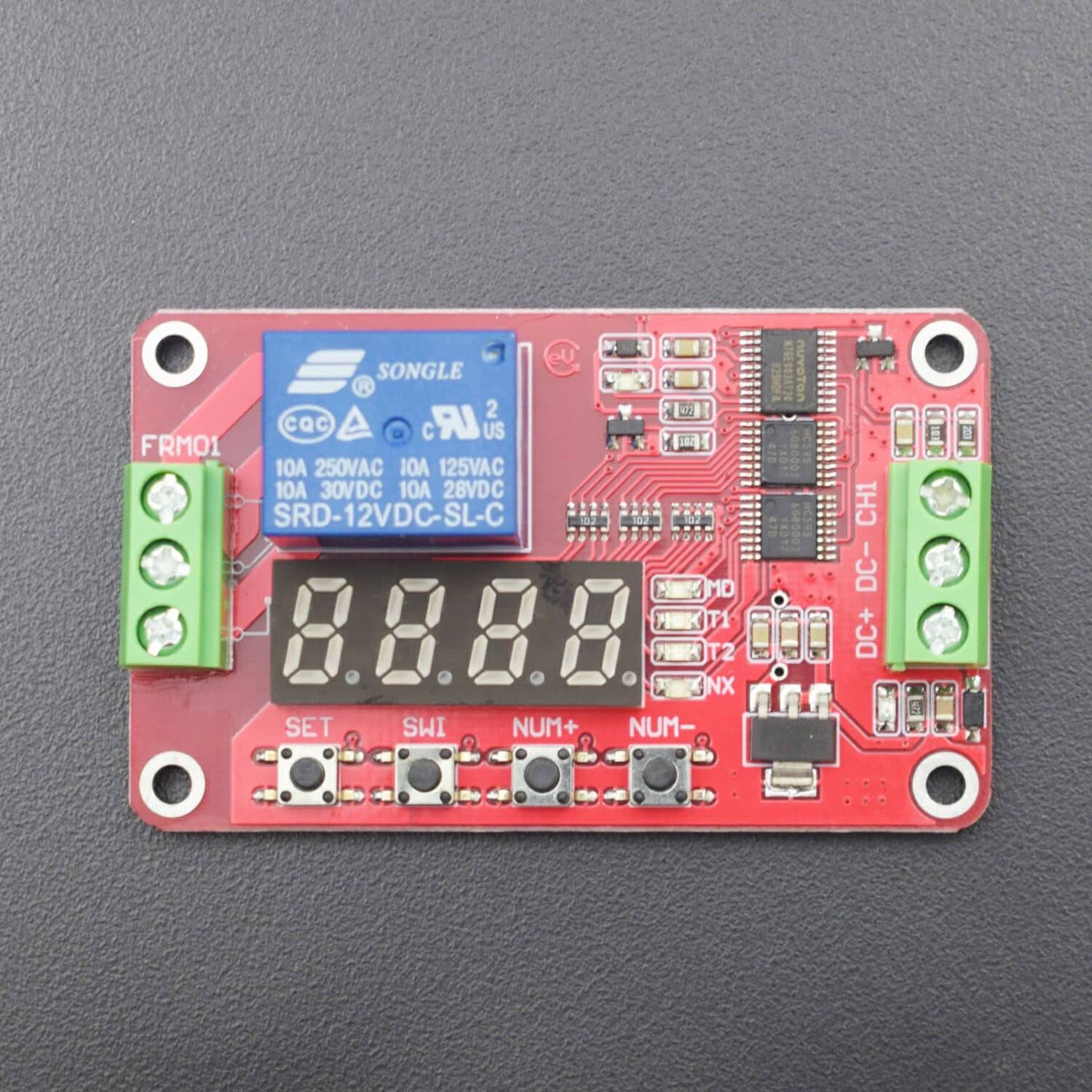
MODULE INTERFACE
- DC +: DC power positive
- DC-: DC power supply negative
- CH1: an input signal detection interface
- CH2: Input Signal Detection Interface 2