


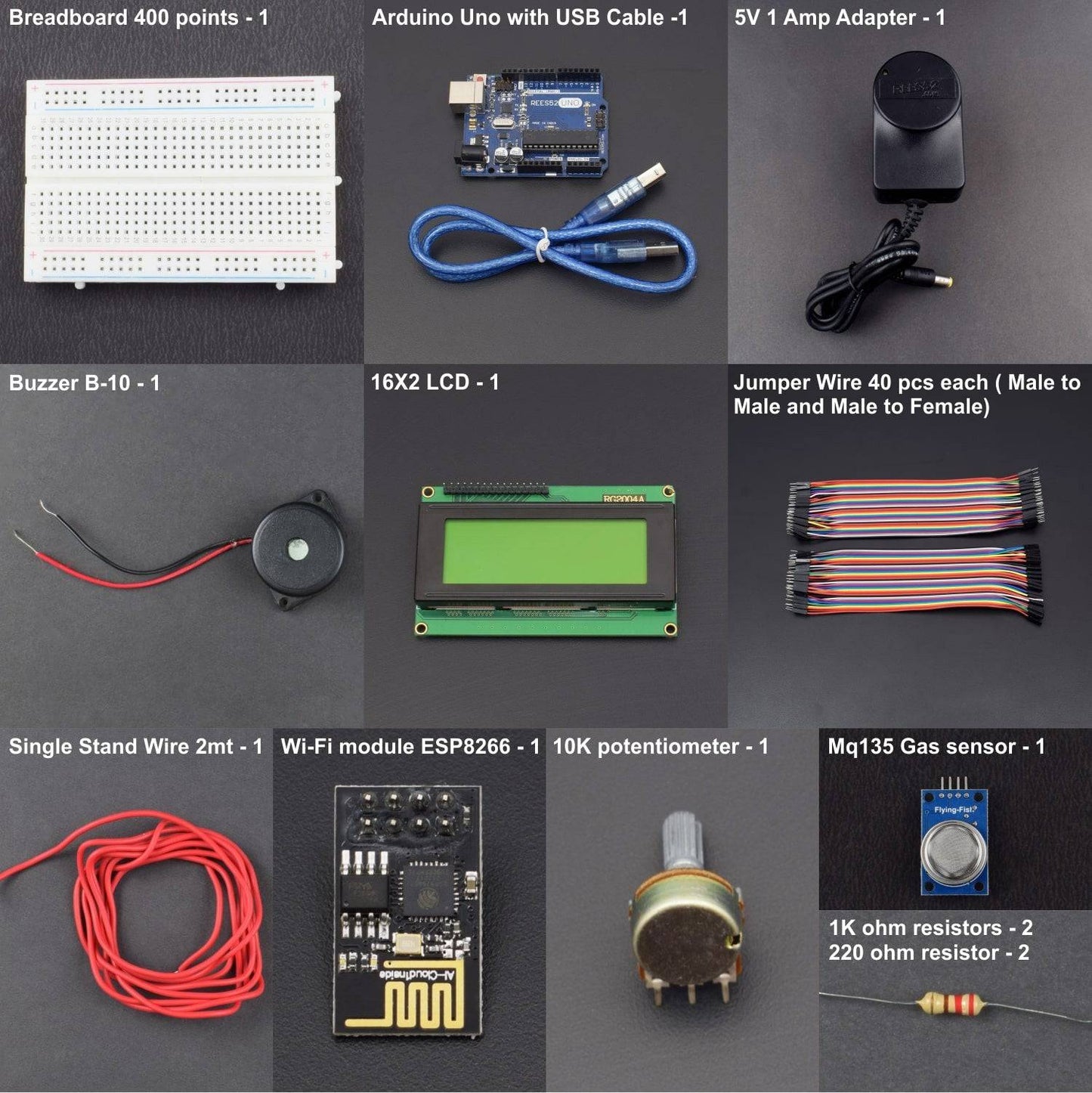


- MQ135 Gas sensor - 1
- Arduino Uno with USB Cable -1
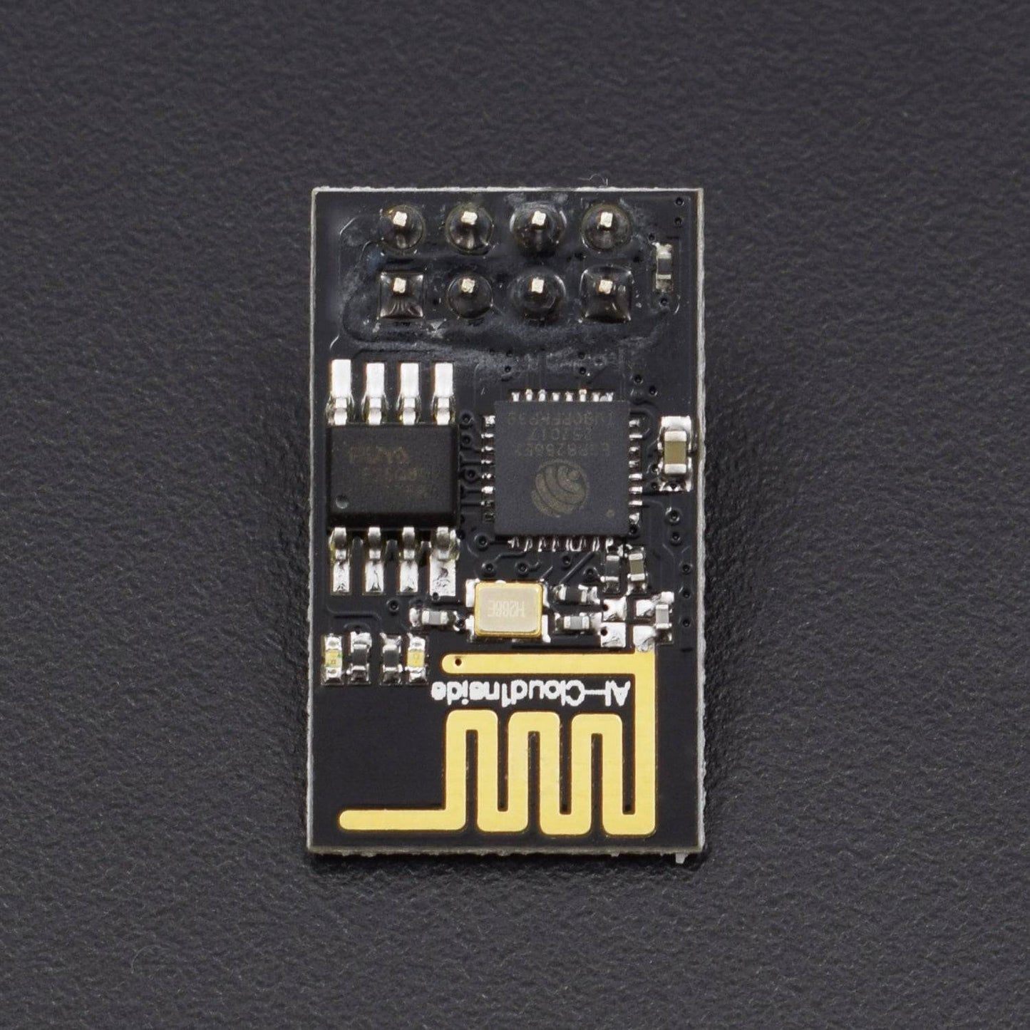
- Wi-Fi module ESP8266 – 01 - 1
- 16X2 LCD - 1
- Breadboard 400 points - 1
- 10K potentiometer - 1
- 1K ohm resistors - 2
- 220 ohm resistor - 2
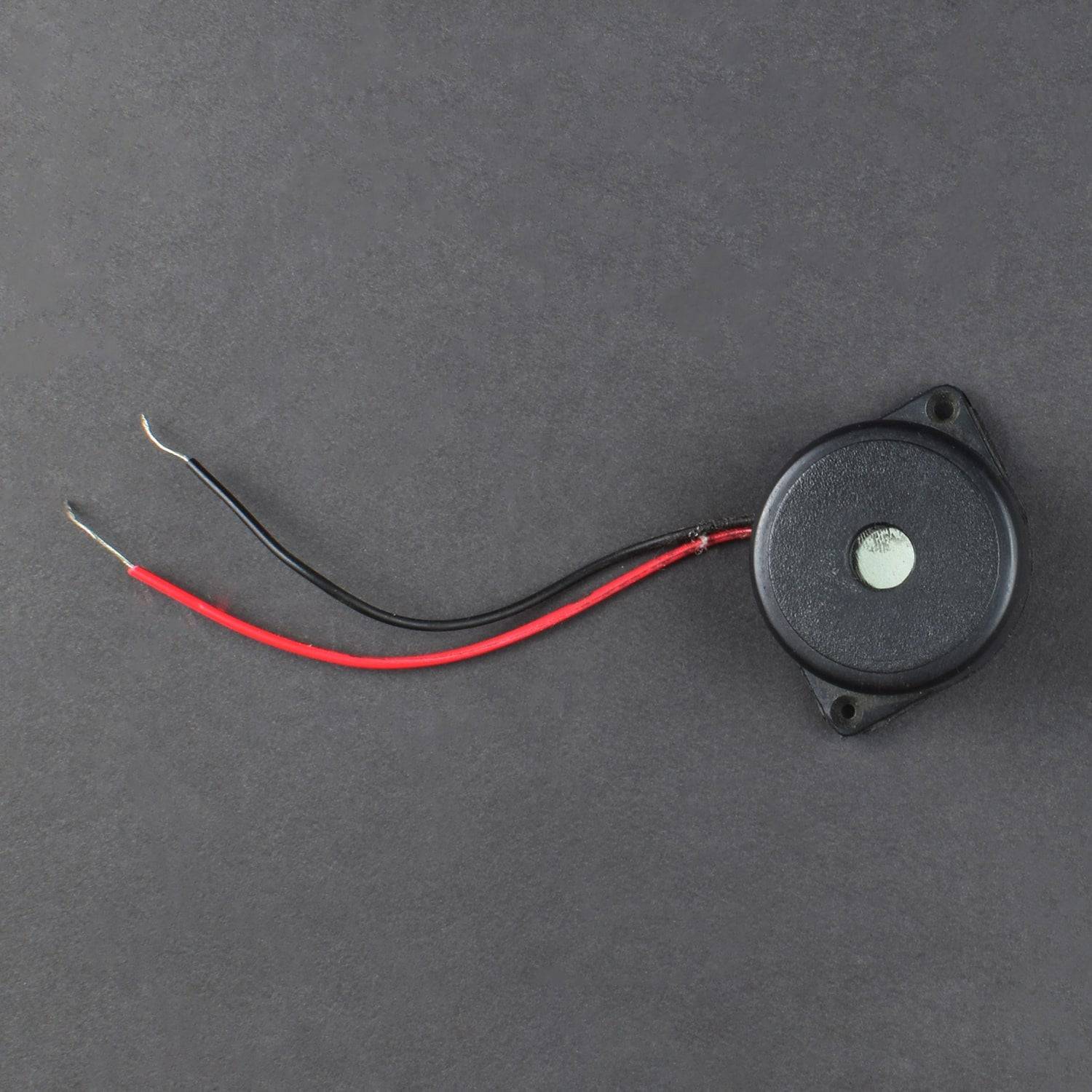
- Buzzer B-10 – 1
- Jumper wire male to female – 40 pieces
- Jumper wire male to male – 40 pieces
In this project we are going to make an IOT Based Air Pollution Monitoring System in which we will monitor the Air Quality over a webserver using internet and will trigger an alarm when the air quality goes down beyond a certain level, means when there are sufficient amount of harmful gases are present in the air like CO2, smoke, alcohol, benzene and NH3. It will show the air quality inPPM on the LCD and as well as on webpage so that we can monitor it very easily.
HARDWARE REQUIRED
- MQ135 Gas sensor - 1
- Arduino Uno with USB Cable -1
- Wi-Fi module ESP8266 – 01 - 1
- 16X2 LCD - 1
- Breadboard 400 points - 1
- 10K potentiometer - 1
- 1K ohm resistors - 2
- 220 ohm resistor - 2
- Buzzer B-10 – 1
- Jumper wire male to female – 40 pieces
- Jumper wire male to male – 40 pieces
SOFTWARE REQUIRED
Arduino IDE 1.8.5 (programmable platform for Arduino)
Click To Download :https://www.arduino.cc/en/Main/Software

SPECIFICATIONS
ESP8266 Wi-fi Module
The ESP8266 Wi-Fi Module is a self-contained SOC with integrated TCP/IP protocol stack that can give any microcontroller access to your Wi-Fi network. The ESP8266 is capable of either hosting an application or offloading all Wi-Fi networking functions from another application processor.

16*2 LCD Display


MQ135 gas Sensor

.JPG)
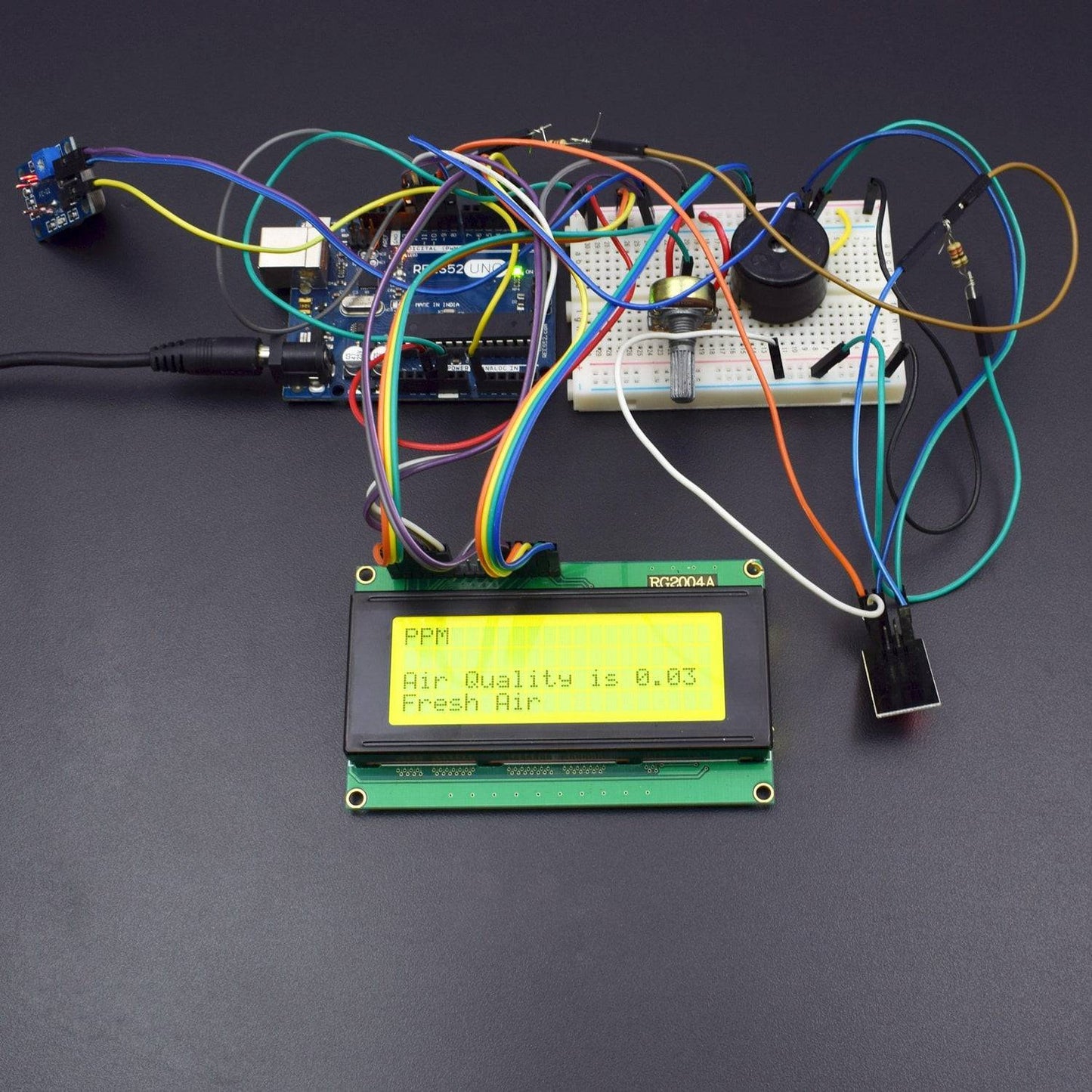
CIRCUIT CONNECTION
First of all we will connect the ESP8266 with the Arduino. ESP8266 runs on 3.3V and if you will give it 5V from the Arduino then it won’t work properly and it may get damage. Connect the VCC and the CH_PD to the 3.3V pin of Arduino. The RX pin of ESP8266 works on 3.3V and it will not communicate with the Arduino when we will connect it directly to the Arduino. So, we will have to make a voltage divider for it which will convert the 5V into 3.3V. This can be done by connecting three resistors in series like we did in the circuit. Connect the TX pin of the ESP8266 to the pin 10 of the Arduino and the RX pin of the esp8266 to the pin 9 of Arduino through the resistors.
ESP8266 Wi-Fi module gives your projects access to Wi-Fi or internet.
Then we will connect the MQ135 sensor with the Arduino. Connect the VCC and the ground pin of the sensor to the 5V and ground of the Arduino and the Analog pin of sensor to the A0 of the Arduino.
Connect a buzzer to the pin 8 of the Arduino which will start to beep when the condition becomes true.
The connections of the LCD are as follows
- Connect pin 1 (VEE) to the ground.
- Connect pin 2 (VDD or VCC) to the 5V.
- Connect pin 3 (V0) to the middle pin of the 10K potentiometer and connect the other two ends of the potentiometer to the VCC and the GND. The potentiometer is used to control the screen contrast of the LCD. Potentiometer of values other than 10K will work too.
- Connect pin 4 (RS) to the pin 12 of the Arduino.
- Connect pin 5 (Read/Write) to the ground of Arduino. This pin is not often used so we will connect it to the ground.
- Connect pin 6 (E) to the pin 11 of the Arduino. The RS and E pin are the control pins which are used to send data and characters.
The following four pins are data pins which are used to communicate with the Arduino.
- Connect pin 11 (D4) to pin 5 of Arduino.
- Connect pin 12 (D5) to pin 4 of Arduino.
- Connect pin 13 (D6) to pin 3 of Arduino.
- Connect pin 14 (D7) to pin 2 of Arduino.
- Connect pin 15 to the VCC through the 220 ohm resistor. The resistor will be used to set the back light brightness. Larger values will make the back light much more darker.
- Connect pin 16 to the Ground.

CODE
CLICK TO SEE THE CODE:
TESTING AND OUTPUT
Before uploading the code, make sure that you are connected to the Wi-Fi of your ESP8266 device. After uploading, open the serial monitor and it will show the IP address like shown below.

Type this IP address in your browser, it will show you the output as shown below. You will have to refresh the page again if you want to see the current Air Quality Value in PPM.

We have setup a local server to demonstrate its working, you can check the Video below. But to monitor the air quality from anywhere in the world, you need to forward the port 80 (used for HTTP or internet) to your local or private IPaddress (192.168*) of you device. Afterport forwarding all the incoming connections will be forwarded to this local address and you can open above shown webpage by just entering the public IP address of your internet from anywhere. You can forward the port by logging into your router (192.168.1.1) and find the option to setup the port forwarding.
WORKING
In this project we are going to make an IOT Based Air Pollution Monitoring System in which we will monitor the Air Quality over a webserver using internet and will trigger a alarm when the air quality goes down beyond a certain level, means when there are sufficient amount of harmful gases are present in the air like CO2, smoke, alcohol, benzene and NH3. It will show the air quality in PPM on the LCD and as well as on webpage so that we can monitor it very easily.
The MQ135 sensor can sense NH3, NOx, alcohol, Benzene, smoke, CO2 and some other gases, so it is perfect gas sensor for our Air Quality Monitoring Project. When we will connect it to Arduino then it will sense the gases, and we will get the Pollution level in PPM (parts per million). MQ135 gas sensor gives the output in form of voltage levels and we need to convert it into PPM. So for converting the output in PPM, here we have used a library for MQ135 sensor, it is explained in detail in “Code Explanation” section below.
Sensor was giving us value of 90 when there was no gas near it and the safe level of air quality is 350 PPM and it should not exceed 1000 PPM. When it exceeds the limit of 1000 PPM, then it starts cause Headaches, sleepiness and stagnant, stale, stuffy air and if exceeds beyond 2000 PPM then it can cause increased heart rate and many other diseases.
When the value will be less than 1000 PPM, then the LCD and webpage will display “Fresh Air”. Whenever the value will increase 1000 PPM, then the buzzer will start beeping and the LCD and webpage will display “Poor Air, Open Windows”. If it will increase 2000 then the buzzer will keep beeping and the LCD and webpage will display “Danger! Move to fresh Air”.