


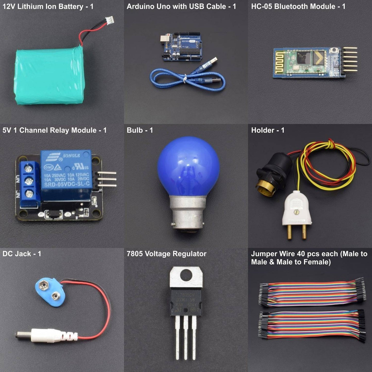
KIT INCLUDES:
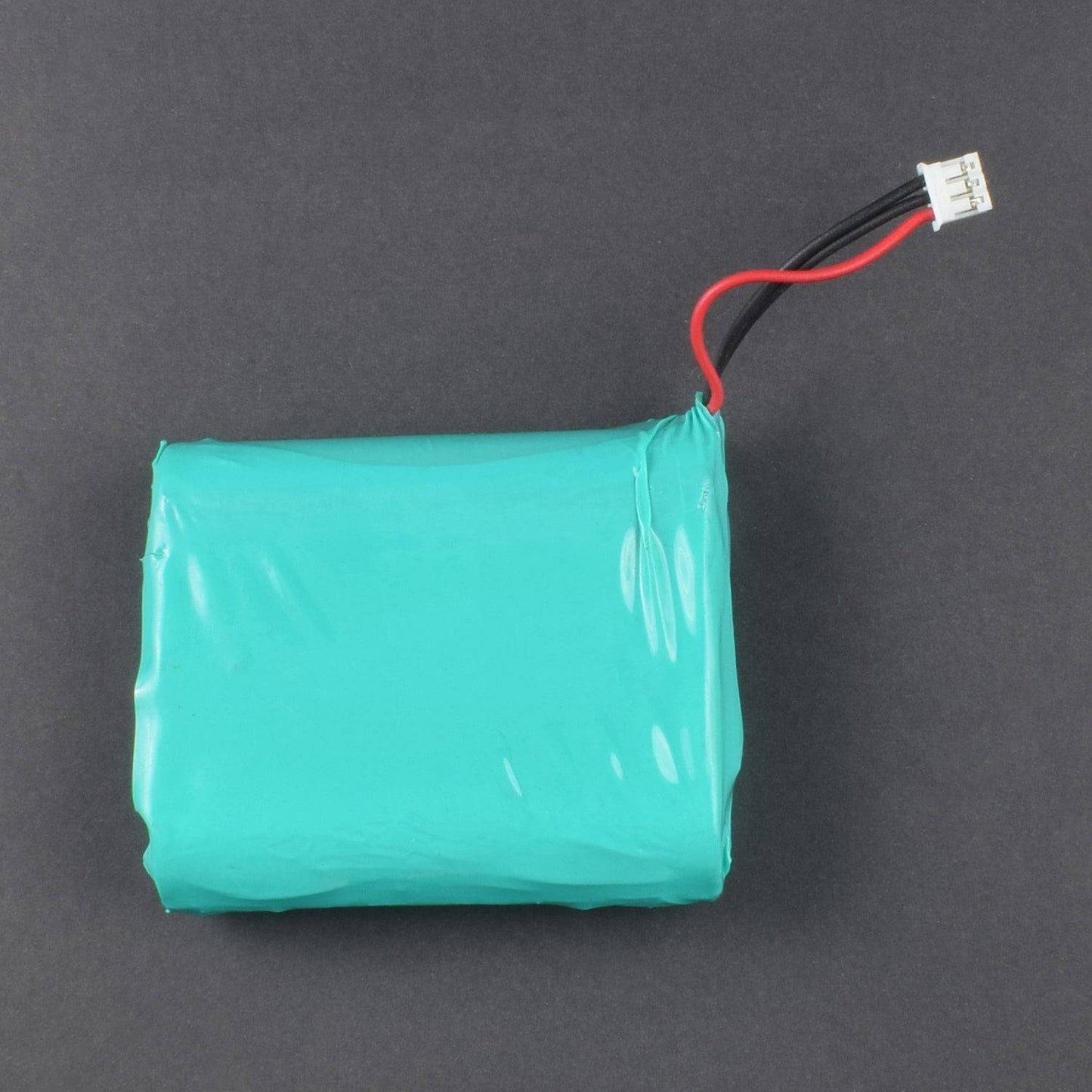
- 12V Lithium-Ion Battery – 1
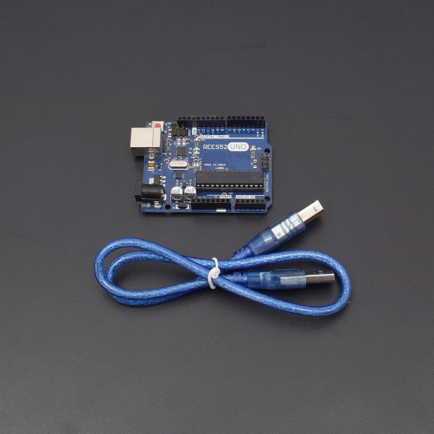
- Arduino uno with USB Cable – 1
- HC-05 Bluetooth Module – 1
- 5v 1 Channel Relay module – 1
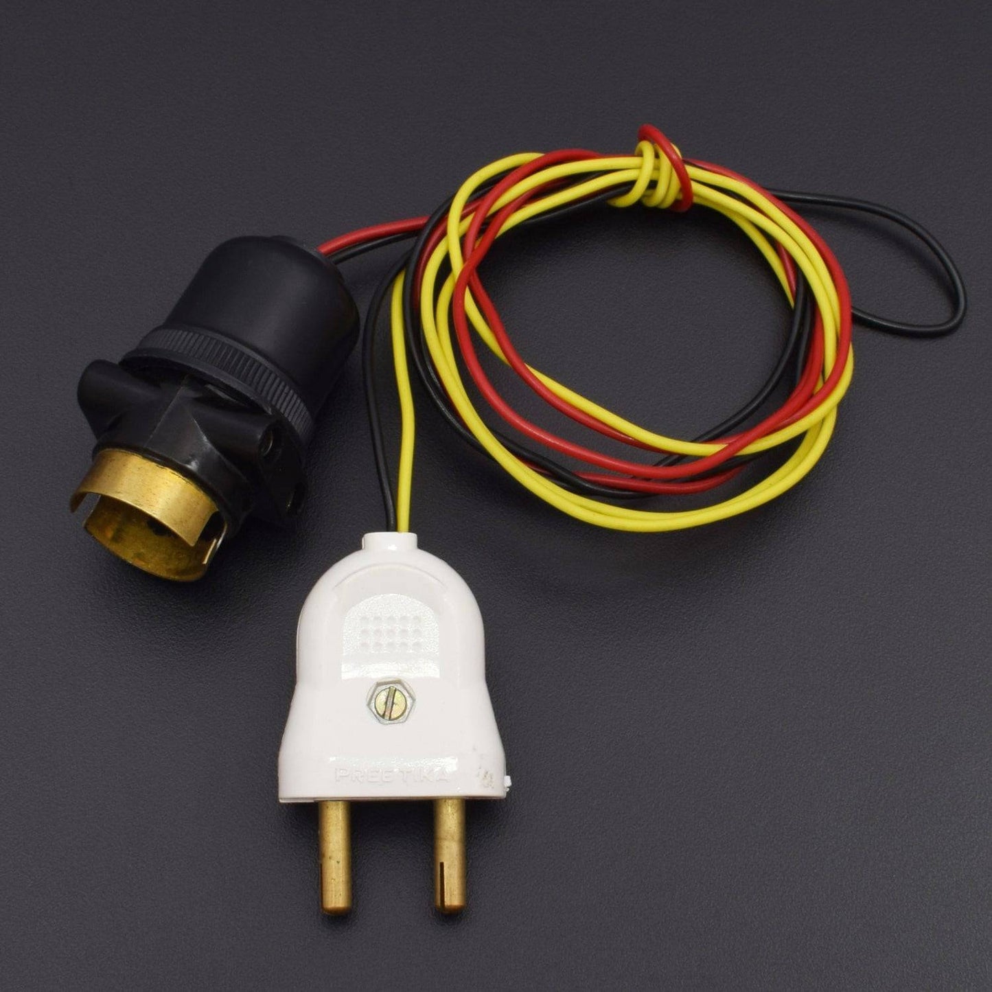
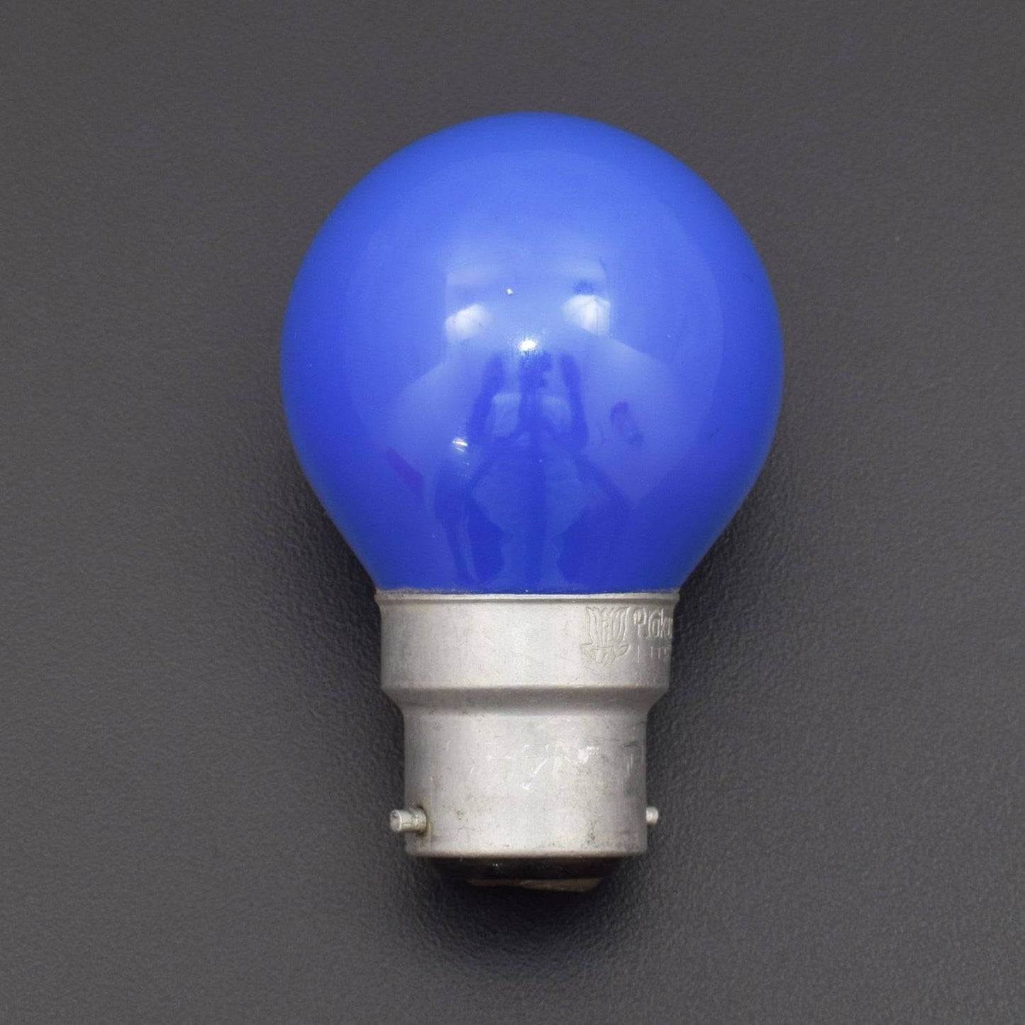
- Bulb – 1(Not included in kit)
- Holder - 1(Not included in kit)
- Battery snapper with DC jack – 1
- 7805 Voltage Regulator – 1
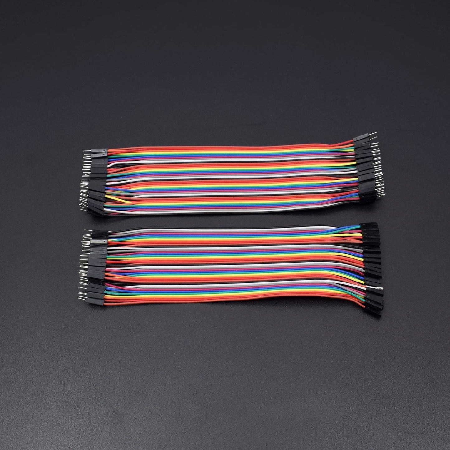
- Jumper wire male to female– 40 pieces
- Jumper wire male to male – 40
HARDWARE REQUIRED
- 12V Lithium-Ion Battery – 1
- Arduino uno with USB Cable – 1
- HC-05 Bluetooth Module – 1
- 5v 1 Channel Relay module – 1
- Bulb – 1(Not included in kit)
- Holder - 1(Not included in kit)
- Battery snapper with DC jack – 1
- 7805 Voltage Regulator – 1
- Jumper wire male to female– 40 pieces
- Jumper wire male to male – 40
SOFTWARE REQUIRED
Arduino IDE 1.8.5 (programmable platform for Arduino)
Click To Download :https://www.arduino.cc/en/Main/Software

SPECIFICATIONS
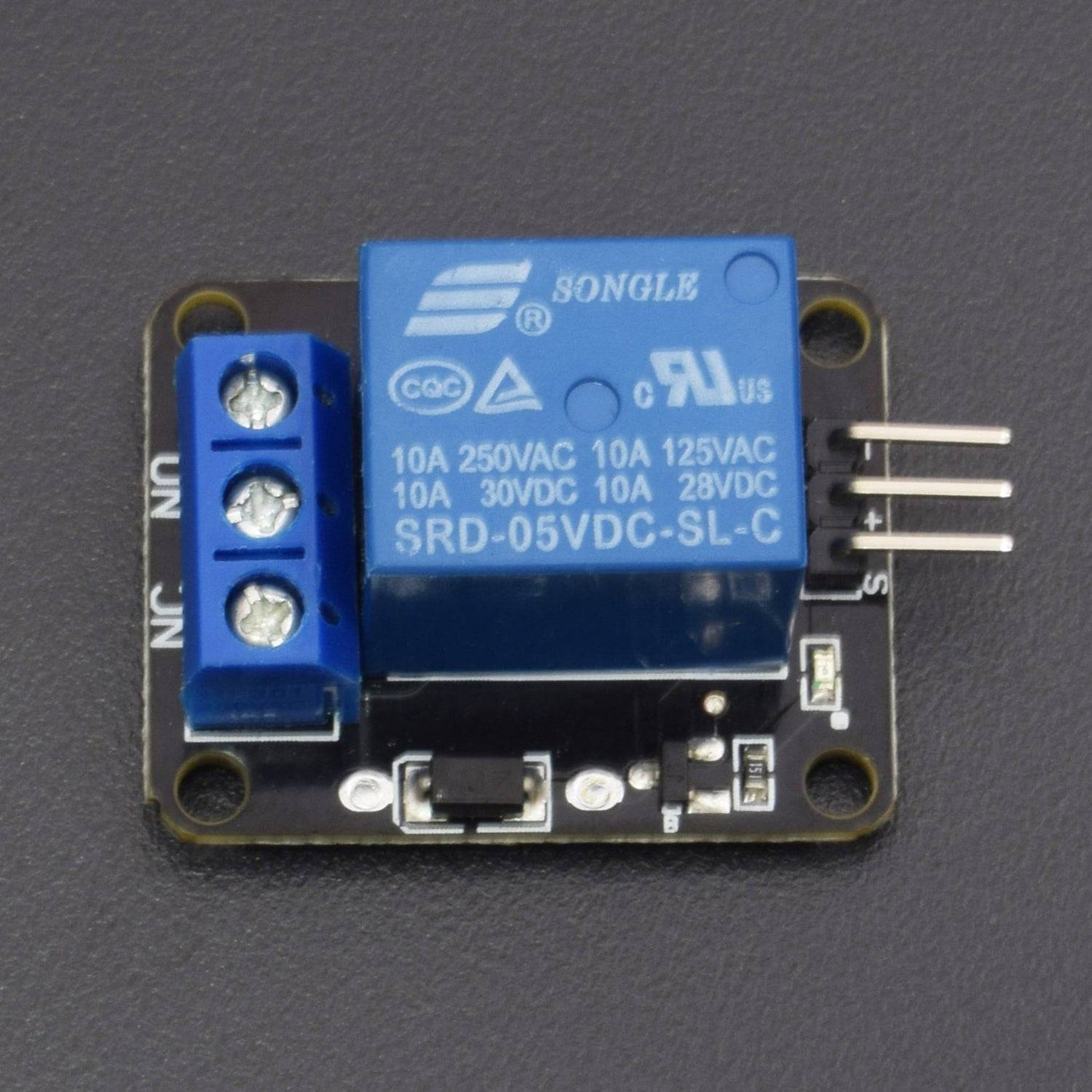
5V RELAY MODULE

- Number of I/O Channels: 1
- Type: Digital
- Control signal: TTL level
- Max. Allowable Voltage: 250VAC/110VDC
- Max. Allowable Power Force: From C(800VAC/240W), From A(1200VA/300W)

HC05 BLUETOOTH MODULE

HC‐05 module is an easy to use Bluetooth SPP (Serial Port Protocol) module, designed for transparent wireless serial connection setup. The HC-05 Bluetooth Module can be used in a Master or Slave configuration, making it a great solution for wireless communication. This serial port Bluetooth module is fully qualified Bluetooth V2.0+EDR (Enhanced Data Rate) 3Mbps Modulation with complete 2.4GHz radio transceiver and baseband.
Sensitivity |
-80 dBm |
Transmit Power |
Up to +4 dBm |
Low power Operation |
1.8 to 3.6 V I/O |
Interface |
UART interface with programmable baud rate |
Control |
PIO (program input/output) |
PIN NAME |
DESCRIPTION |
Vcc |
Connects to 5v of positive voltage for power |
Trig |
A pulse is sent here for the sensor to go into the ranging mode for object detection |
Echo |
The Echo sends a signal back if an object has been detected or not. if a signal is returned, an object has been detected, If not, no object has been detected. |
Gnd |
Completes electrical pathway of the power. |
|
How to operate Bluetooth module? You can directly use the Bluetooth module after purchasing from the market because there is no need to change any setting of Bluetooth module. Default baud rate for new Bluetooth module is 9600 bps. You just need to connect RX and TX to the controller or serial converter and give 5-volt dc regulated power supply to the module. Bluetooth module has two modes one is master mode and the second one is slave mode. The user can set either mode by using some AT commands. Even user can set module’s setting by using AT command. Here are some commands uses are given: First of all, the user needs to enter AT mode with 38400 bps baud (you can set it to 9600 if you are not able to run the code) rate by pressing EN button at Bluetooth module and by giving HIGH level at EN pin. Note: all commands should end with rn (0x0d and 0x0a) or ENTER KEY from the keyboard. After it, if you send AT to module then module will respond with OK |
Default Software Features
- Slave default Baud rate: 9600, Data bits: 8, Stop bit: 1, Parity: No parity.
- Auto‐connect to the last device on power as default.
- Permit pairing device to connect as default.
- Auto‐pairing PINCODE:”1234” as default.
|
AT → Test Command AT+ROLE=0 → Slave Mode select AT+ROLE=1 → Master Mode select AT+NAME=xyz → Set Bluetooth Name AT+PSWD=xyz → Set Password AT+UART= Eg. AT+UART=9600,0,0
|
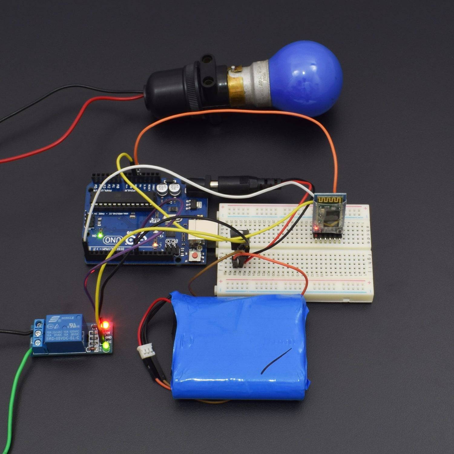
CIRCUIT CONNECTION
Note: You can use 1 Channel relay or more according to you. Here we are using one bulb so you can add one extra bulb for presentation.

The Digital Pins 10 to 13 are used to control the Relay Board. The Transmit pin of Bluetooth Module is connected to the receive pin of Arduino.
Our Home Appliances will be connected to the Relay Board the above figure can be used explain the working of a Relay board. I took a Single Channel relay board for the simplicity. A relay is having two parts.
INPUT and OUTPUT.
Input part is having three pins. The Signal Trigger port is used to control (ON and OFF Relay). DC- and DC+ are used to provide the operational voltage for the relay (12V DC).
Output part is having three Ports. AC Positive terminal will be connected to the Common Port. The positive terminal of the Appliance will be connected to the normally open Port and Next end of the Appliance will be grounded.
The common port will get in touch with the normally opened port when the Signal Trigger port gets a Digital High Signal (+5 V). So the Load connected to the Relay board will get powered ON.
Same as the common port will get in touch with the normally closed port when the Signal Trigger port gets a Digital Low Signal (GND V). So the Load connected to the Relay board will get
CODE
WORKING
We explain the Block Diagram for this project before getin to the detailed circuit diagram. Our project is mainly having three block.
1. Bluetooth Module
2. Arduino UNO
3. Relay Board
Bluetooth Module: The Bluetooth Module block is mainly responsible for establishing the connection between The Android Smart phone and the Circuit over Bluetooth Channel.

Arduino UNO: This block is the main part of our project which controls and co-ordinates all the other peripherals that are connected with the circuit.
Relay Board: Relay board is nothing, it is a Magnetic Switch. We are using a 4 channel relay board for this project to control 4 different Appliances.

We are using an Android Application Named: Bluetooth Control for Arduino for this project that can be downloaded from the Google Play store.
This Application will be used to control our Home Appliances.

Arduino will get ready to receive commands once the Android App successfully paired with the Circuit over the bluetooth channel. Once a button is pressed a value will be sent(Eg:- "A") by the App and it will be received by the Circuit though the Bluetooth Module. The value received by the Bluetooth Module will be sent to the receive port of Arduino.
Arduino will check the Value received and it will Control the Relay according to that. The actual values that I am using for this project is listed below.
Relay 1 is on= "1"
Relay 2 is on= "2"
Relay 3 is on= "3"
Relay 4 is on= "4"
Relay 1 is OFF="A"
Relay 2 is OFF="B"
Relay 3 is OFF="C"
Relay 4 is OFF="D"
All Relay ON= "9"
All Relay OFF= "I"