


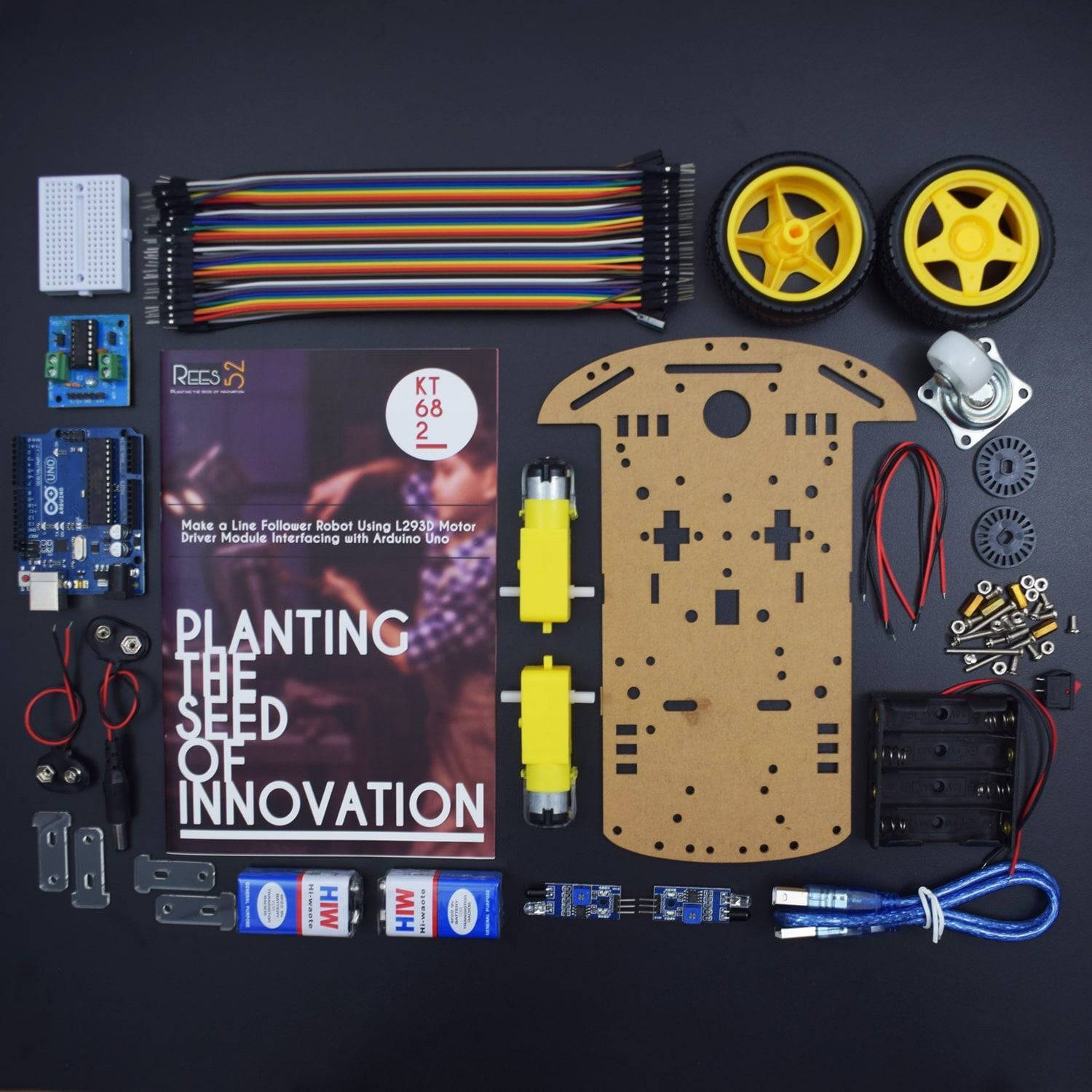


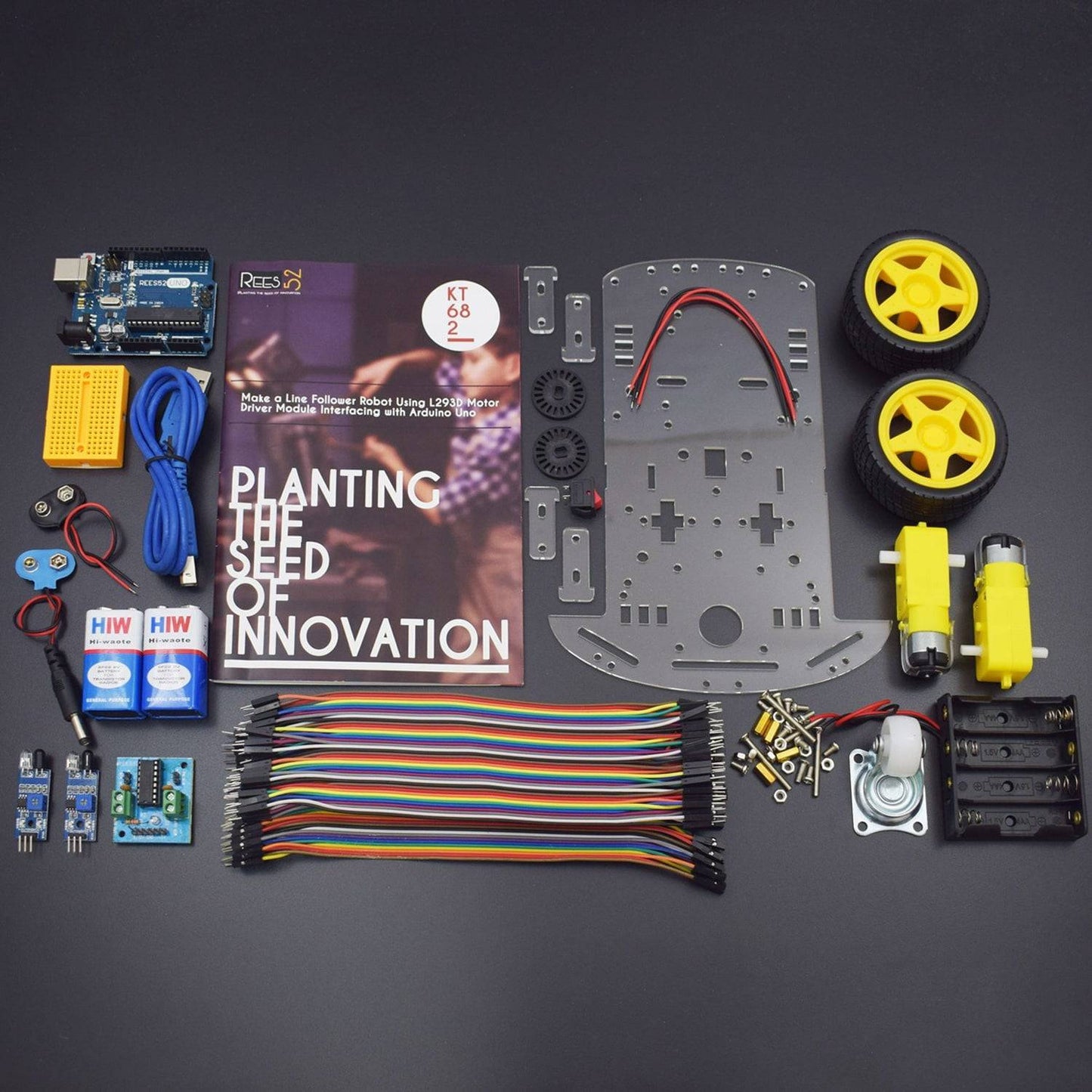

KIT INCLUDED:
- Arduino Uno with USB cable - 1
- IR Sensor Module - 2
- Jumper wires (male to male ) – 40 pieces
- Jumper wires (male to female ) – 40 pieces
- 9V Battery - 2
- Snapper with DC Jack – 1
- Snapper - 1
- Breadboard 170 points – 1
- L293D Motor Driver Module – 1
- Two Wheel Car Chassis - 1
HARDWARE REQUIRED
- Arduino Uno with USB cable - 1
- IR Sensor Module - 2
- Jumper wires (male to male ) – 40 pieces
- Jumper wires (male to female ) – 40 pieces
- 9V Battery - 2
- Snapper with DC Jack – 1
- Snapper - 1
- Breadboard 170 points – 1
- L293D Motor Driver Module – 1
- Two Wheel Car Chassis - 1
SOFTWARE REQUIRED
Arduino IDE 1.8.5 (programmable platform for Arduino)
Click To Download:https://www.arduino.cc/en/Main/Software
SPECIFICATIONS
L293D Motor Driver Module
This particular Motor Driver Module is a quadruple high-current half-H driver.
- Supply-Voltage: 5 V
- VSS Power Supply: 36 V
- Separate Input-Logic Supply
- Thermal Shutdown
- Output Current 600 mA Per Channel
- Highest Output Current 1.2 A Per Channel
IR Sensor Module
This particular Sensor Module has a built-in IR transmitter and IR receiver that sends out IR energy and looks for reflected IR energy to detect presence of any obstacle in front of the sensor module. The module has on board potentiometer that lets user adjust detection range. The sensor has very good and stable response even in ambient light or in complete darkness.
- Operating Voltage: 3.3V – 5.0V
- Detection range:2cm – 30cm (Adjustable using potentiometer)
- Current Consumption:at 3.3V : ~23 mA,at 5.0V: ~43 mA
- Active output level: Outputs Low logic level when obstacle is detected
- On board Obstacle Detection LED indicator
PIN DESCRIPTION
IR Sensor Module
Pin |
Name |
Description |
1 |
GND |
Ground (It grounds the Input and completes the circuit path) |
2 |
VCC |
3.3V to 5V (Recommended Voltage) |
3 |
OUT |
Output Pin that goes low when Obstacle is in range |
4 |
Power LED |
Illuminates when power is Applied |
5 |
Obstacle LED |
Illuminates when the obstacle is detected |
6 |
Distance Adjust |
Adjust detection Distance. |
7 |
IR Emitter |
Infrared Emitter LED |
8 |
IR Receiver |
The infrared receiver that receives the signal transmitted by the Infrared Emitter |

L293D Motor Driver Module
Pin |
Name |
Description |
1 |
GND Pin |
Ground (It grounds the Input and completes the circuit path) |
2 |
+5V Pin |
It is the Recommended Voltage |
3 |
+9/12V Pin (VSS) |
It is Recommended Power Supply(36V is Maximum) |
4 |
Power LED |
Illuminates when power is Applied |
5 |
IN1 Pin |
Input Pin1 (To rotate the motor in a Clock-wise direction. It is for Motor1 Inputs) |
6 |
MTR1 Pin |
It is for the Input of Motor 1 |
7 |
IN2 Pin |
Input Pin2 (To rotate the motor in an Anti-clockwise direction. It is for Motor1 Inputs) |
8 |
MTR2 Pin |
It is for the Input of Motor 2 |
9 |
Motor Driving IC |
It consists of two H-Bridge circuit inside the IC which can rotate two dc motor independently. |

CIRCUIT CONNECTION
NOTE - Before Making the circuit must check the IR Sensor Module range. You Can adjust the sensitivity by rotating inbuilt potentiometer on above the IR Sensor.
IR SENSOR TESTING
| PIN (IR SENSOR) | ARDUINO UNO |
| OUT | Digital pin 7 |
| GND | Gnd |
| VCC | 5v |

CLICK TO SEE THE CODE TO CHECK THE RANGE FOR IR SENSOR

When the full circuit is done and the code set is also done. Now, time to connect the Board to the Computer using the USB jack. Once connected to suppose COM3 port, open the Arduino Set up IDE where the code set up is done, compile the code once and then Upload the code to the Board. Once Upload is done the TX RX LEDs blink quick.
Now we are all set to test the sensor. For better and precise testing, we can solder the wires (jumper wires) to the sensors as their connected pins are not portable. The whole set-up can be soldered.
Then when we connect, open up the Serial port screen which transmits at 9600 bits per sec and checks the message, as per written in the program.
As per the program, the LED also blinks and illuminates based on the Obstacle sensor output.
The serial screen would look like above.
NOW, You are Ready to make a Line follower Robot Car
Let's Make a Line Follower
- The GND Pin of the IR Sensor Module 1 is being attached to the GND Pin of Arduino Uno.
- The VCC Pin of IR Sensor Module 1 is connected with the 5V Pin of Arduino Uno.
- The OUT Pin of IR Sensor Module 1 is connected with the Analog Pin A0 of the Arduino Uno.
- The GND Pin of the IR Sensor Module 2 is being attached to the GND Pin of Arduino Uno.
- The VCC Pin of IR Sensor Module 2 is connected with the 5V Pin of Arduino Uno.
- The OUT Pin of IR Sensor Module 2 is connected with the Analog Pin A1 of the Arduino Uno.
- The GND Pin of the L293D Motor Driver Module is being attached to the GND Pin of Arduino Uno.
- The +5V Pin of the L293D Motor Driver Module is connected with the 5V Pin of Arduino Uno.
- The IN2 Pin of L293D Motor Driver Module is being connected to the Digital Pin 8 of the Arduino Uno.
- The MTR2 Pin of L293D Motor Driver Module is being connected to the Digital Pin 9 of the Arduino Uno.
- The MTR1 Pin of L293D Motor Driver Module is being connected to the Digital Pin 10 of the Arduino Uno.
- The IN1 Pin of L293D Motor Driver Module is being connected to the Digital Pin 11 of the Arduino Uno.
- Connect 9/12V Power Supply to the 9/12V Pin of the L293D Motor Driver Module. Here, we are using 9V Battery for Power Supply.

Sno. |
Arduino Pin |
L293D Motor |
IR Sensor 1 |
IR Sensor 2 |
1 |
GND Pin |
GND Pin |
GND Pin |
GND Pin |
2 |
+5V Pin |
+5V Pin |
VCC Pin |
VCC Pin |
3 |
Analog Pin A0 |
- |
OUT Pin |
- |
4 |
Analog Pin A1 |
- |
- |
OUT Pin |
5 |
Digital Pin 8 |
IN2 Pin |
- |
- |
6 |
Digital Pin 9 |
MTR2 Pin |
- |
- |
7 |
Digital Pin 10 |
MTR1 Pin |
- |
- |
8 |
Digital Pin 11 |
IN1 Pin |
- |
- |
CODE
Click to see code here: https://docs.google.com/document/d/e/2PACX-1vSq0s5VNdvPdTUKbLJSEgw---a-jxrawlOrmTE6Y0GEG7Rn-Abi573OQUQCrLXTfLw8MPTsCHdHe_Z1/pub?embedded=true
WORKING

Welcome to this Arduino based Line Follower Robot which consists of IR Sensors and L293D Motor Driver Module. In this particular circuit we have used various components for specified purposes:
- Sensors: Here, IR Sensor Module is used as the line detecting sensor for the project. It consists of an IR LED and a Photo diode and some other components like comparator, LED etc as given in Pin description.
- Controller: Here, Arduino UNO is used as the main controller of the project. The data from the sensors (IR Sensors) is transmitted to the Arduino Uno and it gives corresponding signals to the L293D Motor Driver Module.
- Motor Driver Module: Here, L293D Motor Driver Module is being used to drive the motors of the robot. It receives signals from Arduino Uno Board based on the information passed by the IR Sensors.
NOTE: You can make your own IR Sensor using the Following circuit.

Now, as shown in the Block diagram, sensors are needed to detect the line. The basic working principle for line detection is that the two IR Sensors we used, consists of IR LED and Photodiode. And they are placed in a reflective way i.e. side – by – side so that whenever they come in to proximity of a reflective surface, the light emitted by IR LED will be detected by Photo diode.
Here’s the working of a IR Sensor (IR LED – Photodiode pair) in front of a light coloured surface and a black surface. As the reflectance of the light coloured surface is high, the infrared light emitted by IR LED will be maximum reflected and will be detected by the Photodiode.

But, in the case of Black Surface, there would be less reflectance and the light gets completely absorbed by the Black Surface and doesn’t reach Photodiode. Here is the diagrammatic description of the Forward Movement of the Robot.

When the robot moves forward, both the sensors wait for the line to be detected. When the line is detected, then Arduino UNO detects this change and sends the signal to the motor driver accordingly. In order to turn right, the motor on the right side of the robot is slowed down using PWM (Digital Pins), while the motor on the left side will run at normal speed.

And when the IR Sensor 2 detects the black line first, it means that there is a left curve ahead and the robot has to turn left. For the robot to turn left, the motor on the left side of the robot is slowed down (or can be stopped completely or can be rotated in opposite direction) and the motor on the right side will run at normal speed.
This way Arduino UNO Board continuously monitors the data from both the sensors and turns the robot as per the line detected by them.