


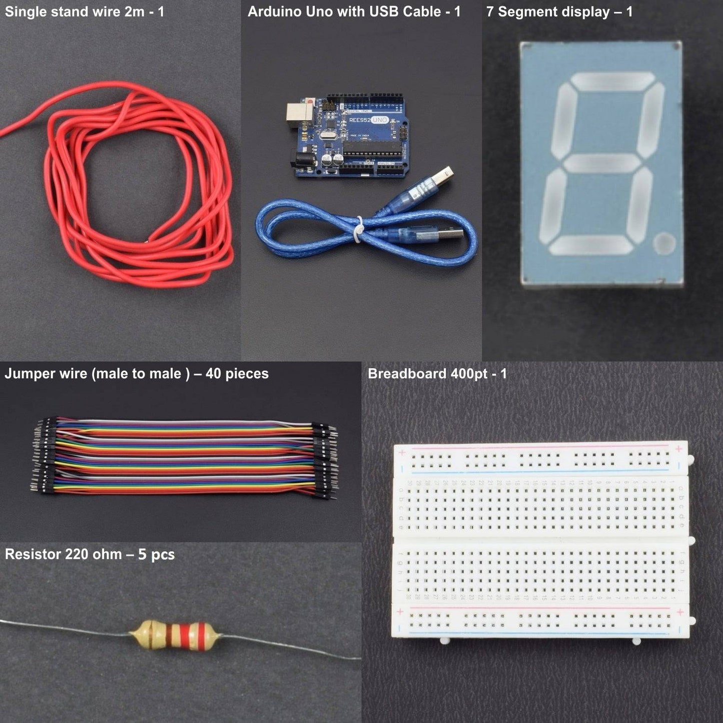

KIT INCLUDES
- Arduino uno with USB Cable – 1
- Resistor 220 ohm – 5 pcs
- Single stand wire 2m - 1
- 7 Segment display – 1
- Jumper wire (male to male ) – 40 pieces
- Breadboard 400 point - 1
Introduction
In this project, we are using 7 segment display to make a countdown launchpad which typically used in space shuttle launch system. Seven segment display is the most common device used for displaying digits and alphabet. One can see a device in TV shows counting down to ‘0’, these are nothing but seven segments.
HARDWARE REQUIRED
- Arduino uno with USB Cable – 1
- Resistor 220 ohm – 5 pcs
- Single stand wire 2m - 1
- 7 Segment display – 1
- Jumper wire (male to male ) – 40 pieces
- Breadboard 400 point - 1
SOFTWARE REQUIRED
Arduino IDE 1.8.5 (programmable platform for Arduino)
Click To Download: https://www.arduino.cc/en/Main/Software


SPECIFICATION
7 segments Led display
.jpg)
Common Anode: All the Negative terminals (cathode) of all the 8 LEDs are connected together. All the positive terminals are left alone.
Common Cathode: All the positive terminals (anode) of all the 8 LEDs are connected together. All the negative thermals are left alone.
1. Common Anode Seven Segment Display
In common anode type, all the anodes of 8 LED’s are connected to the common terminal and cathodes are left free. Thus, in order to glow the LED, these cathodes have to be connected to the logic ‘0’ and anode to the logic ‘1’.

Below truth, the table gives the information required for driving the common anode seven segments.
Segments inputs |
7 Segments Display Output |
||||||
a |
b |
c |
d |
e |
f |
g |
|
0 |
0 |
0 |
0 |
0 |
0 |
1 |
0 |
1 |
0 |
0 |
1 |
1 |
1 |
1 |
1 |
0 |
0 |
1 |
0 |
0 |
1 |
0 |
2 |
0 |
0 |
0 |
0 |
1 |
1 |
0 |
3 |
1 |
0 |
0 |
1 |
1 |
0 |
0 |
4 |
0 |
1 |
0 |
0 |
1 |
0 |
0 |
5 |
0 |
1 |
0 |
0 |
0 |
0 |
0 |
6 |
0 |
0 |
0 |
1 |
1 |
1 |
1 |
7 |
0 |
0 |
0 |
0 |
0 |
0 |
0 |
8 |
0 |
0 |
0 |
0 |
1 |
1 |
0 |
9 |
In order to display zero on this segment, one should enable logic high on a, b, c, d, e and f segments and logic low on segment ‘g’. Thus, the above table provides data on seven segments for displaying numerals from 0-9.
2. Common Cathode Seven Segment Display
As the name indicates cathode is the common pin for this type of seven segments and remaining 8 pins are left free. Here, a logic low is applied to the common pin and logic high to the remaining pins.

Segments inputs |
7 Segments Display Output |
||||||
a |
b |
c |
D |
E |
F |
g |
|
1 |
1 |
1 |
1 |
1 |
1 |
0 |
0 |
0 |
1 |
1 |
0 |
0 |
0 |
0 |
1 |
1 |
1 |
0 |
1 |
1 |
0 |
1 |
2 |
1 |
1 |
1 |
1 |
0 |
0 |
1 |
3 |
0 |
1 |
1 |
0 |
0 |
1 |
1 |
4 |
1 |
0 |
1 |
1 |
0 |
1 |
1 |
5 |
1 |
0 |
1 |
1 |
1 |
1 |
1 |
6 |
1 |
1 |
1 |
0 |
0 |
0 |
0 |
7 |
1 |
1 |
1 |
1 |
1 |
1 |
1 |
8 |
1 |
1 |
1 |
1 |
0 |
0 |
1 |
9 |
Above truth, the table shows the data to be applied to the seven segments to display the digits. In order to display digit‘0’ on seven segments, segments a, b, c, d, e, and f are applied with a logic high and segment g is applied with logic low.
CIRCUIT DESCRIPTION
COMMON CATHODE
.png)
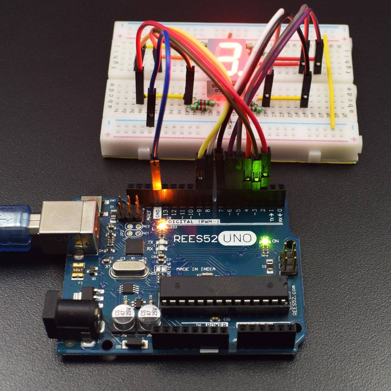
- First, attach the 1 Digit (7 Segment) Display on the Breadboard.
- Connect GND of Arduino Uno with Breadboard for making further GND connections.
- Connect both the GND of 1 Digit (7 Segment) Display with the GND rail of the Breadboard.
- Connect Pins of 1 Digit (7 Segment) Display with Arduino Uno via 220Ω resistor as described in the table below:
Arduino Uno |
7 segment |
| Digital Pin 1 | Led 1 (A) |
| Digital Pin 2 | Led 2 (B) |
| Digital Pin 3 | Led 3 (C) |
Digital Pin 4 |
Led 4 (D) |
| Digital Pin 5 | Led 5 (E) |
| Digital Pin 6 | Led 6 (F) |
| Digital Pin 7 | Led 7 (G) |
Digital Pin 8 |
Led 8 (H) |
COMMON ANODE

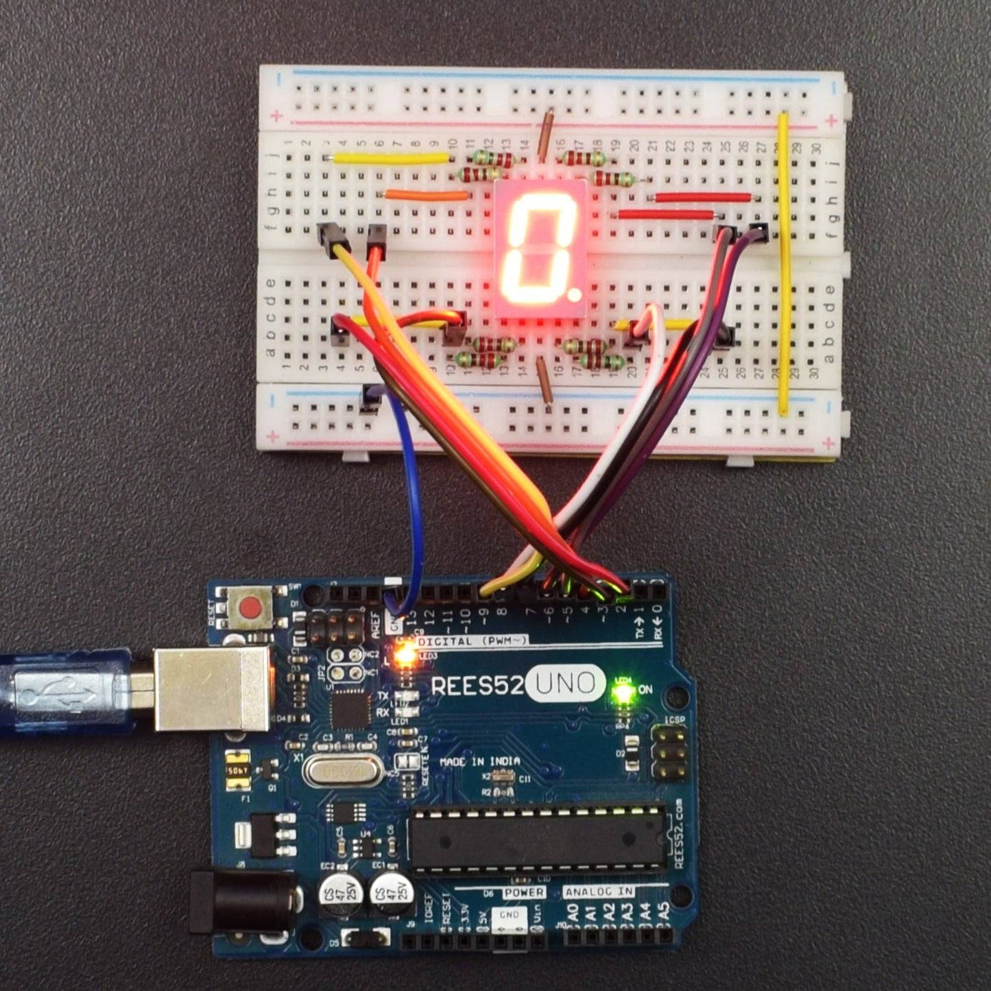
- First, attach the 1 Digit (7 Segment) Display on the Breadboard.
- Connect Pin 3.3V/5V of Arduino Uno with Breadboard for making further 3.3V/5V power supply connections.
- Connect both the Common Pins of 1 Digit (7 Segment) Display with the 3.3V/5V power supply rail of the Breadboard.
- Connect Pins of 1 Digit (7 Segment) Display with Arduino Uno via 220Ω resistor as described in the table below:
Arduino Uno |
7 segment |
| Digital Pin 1 | Led 1 (A) |
| Digital Pin 2 | Led 2 (B) |
| Digital Pin 3 | Led 3 (C) |
Digital Pin 4 |
Led 4 (D) |
| Digital Pin 5 | Led 5 (E) |
| Digital Pin 6 | Led 6 (F) |
| Digital Pin 7 | Led 7 (G) |
Digital Pin 8 |
Led 8 (H) |
CODE
Click to see the code or copy the link:
COMMON CATHODE
COMMON ANODE
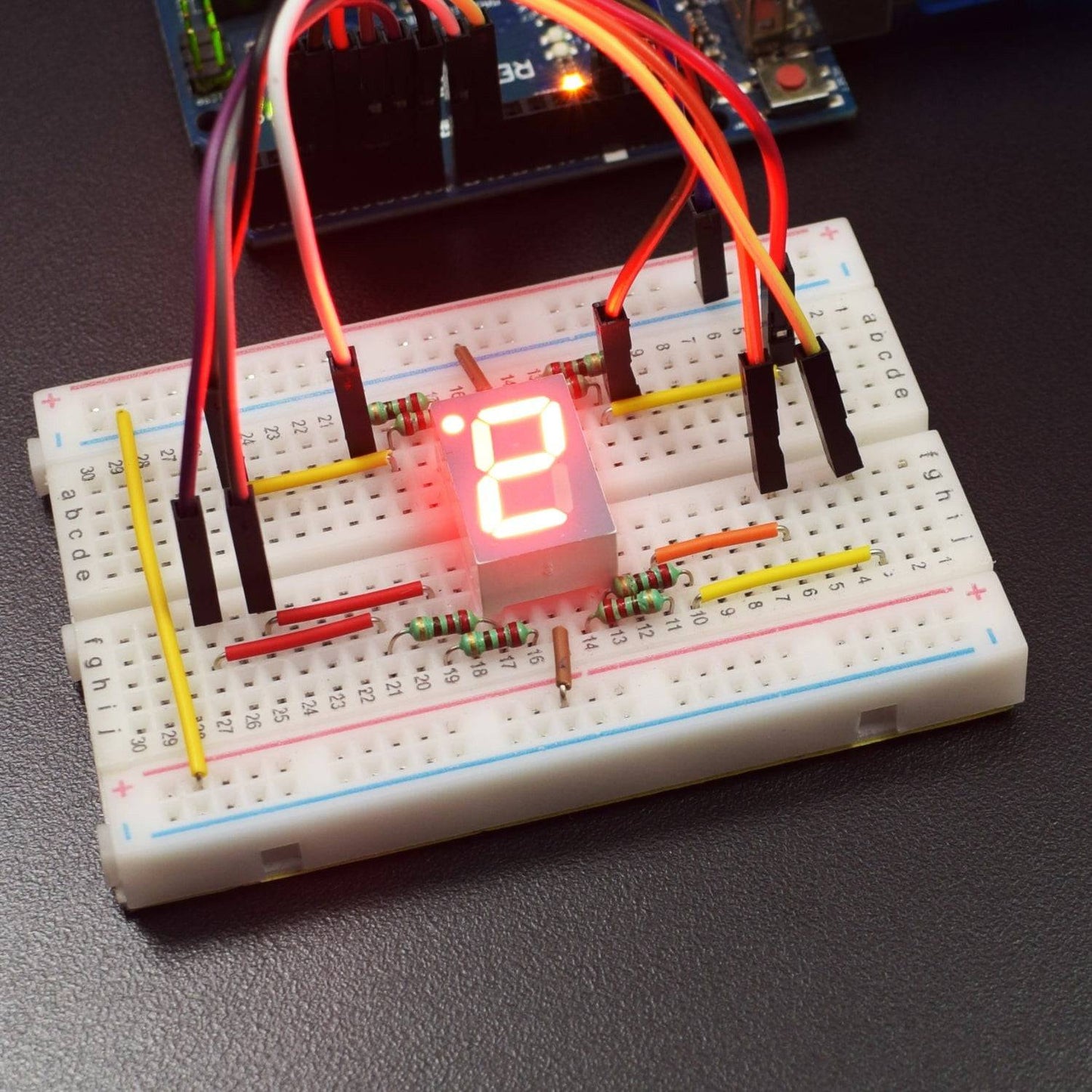
WORKING
Welcome to the Arduino Based Project which consists of Eight Segment Display. The LED segment display is a semiconductor light-emitting device. Its basic unit is a light-emitting diode (LED). LED segment display can be divided into the 7-segment display and 8-segment display according to the number of segments. The 8-segment display has one more LED unit (for decimal point display) than 7-segment one. In this experiment, we use the 8-segment display.
- According to the wiring method of LED units, LED segment displays can be divided into the display with a common anode and display with common cathode.
- Common anode display refers to the one that combines all the anodes of LED units into one common anode (COM).
- For the common anode display, connect the common anode (COM) to +5V.
- When the cathode level of a certain segment is low, the segment is on; when the cathode level of a certain segment is high, the segment is off.
- For the common cathode display, connect the common cathode (COM) to GND.
- When the anode level of a certain segment is high, the segment is on; when the anode level of a certain segment is low, the segment is off. It can have Common cathode 7-segment display and Common anode 7-segment display.
Each segment of the display consists of an LED. So when you use it, you also need to use a current-limiting resistor. Otherwise, LED will be burnt out. In this project, we use a common cathode display. As we mentioned above, for common cathode display, connect the common cathode (COM) to GND.
When the anode level of a certain segment is high, the segment is on; when the anode level of a certain segment is low, the segment is off. There are seven segments for numerical display, one for decimal point display. Corresponding segments will be turned on when displaying certain numbers. For example, when displaying number 1, b and c segments will be turned on. We compile a subprogram for each number and compile the main program to display one number every 2 seconds, cycling display number 0 ~ 9. The displaying time for each number is subject to delay time, the longer the delay time, the longer displaying time. LED segment display displays number 0 to 9.