


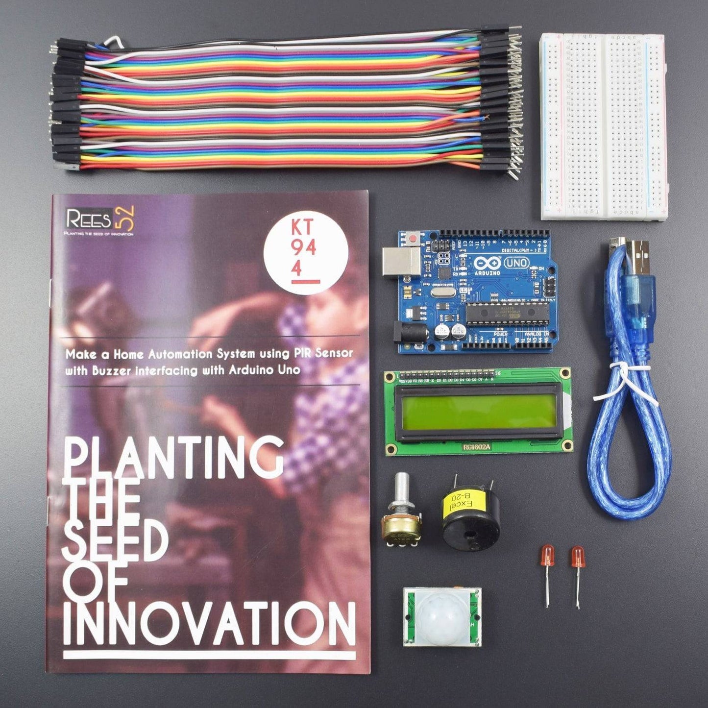


KIT INCLUDES:
- Arduino uno with usb cable - 1
- Breadboard 400 points - 1
- 16*2 lcd display - 1
- Potentiometer 10k – 1
- Jumper wire male to male - 40 pieces
- Jumper wire male to female – 40 pieces
- Piezo Buzzer b20 – 1
- PIR motion Sensor – 1
- Led – 2
- Single stand wire 1mt -1
INTRODUCTION
In this project, we are making a home automation system using PIR sensor with Arduino Uno. Here we are using PIR sensor for sensing human or any other motion, Led, buzzer and LCD as an indicator. When Once there is infrared radiation from the human body/ particle with temperature, focusing on the optical system causes the pyroelectric device to generate a sudden electrical signal
HARDWARE REQUIRED
- Arduino uno with usb cable - 1
- Breadboard 400 points - 1
- 16*2 lcd display - 1
- Potentiometer 10k – 1
- Jumper wire male to male - 40 pieces
- Jumper wire male to female – 40 pieces
- Piezo Buzzer b20 – 1
- PIR motion Sensor – 1
- Led – 2
- Single stand wire 1mt -1
SOFTWARE REQUIRED
Arduino IDE
You can download it from this link: https://www.arduino.cc/en/Main/Software

SPECIFICATIONS
PIR MOTION SENSOR
A PIR(Passive Infrared) sensor is a motion detector which detects the heat (infrared) emitted naturally by humans and animals. When a person in the field of vision of the sensor moves, the sensor detects a sudden change in infrared energy and the sensor is triggered (activated).They are commonly used in security lighting and alarm systems in an indoor environment. The PIR sensors have a range of approximately 6 meters, depending on conditions. The sensor adjusts to slowly changing conditions that occur normally within the environment but shows a high-output response when a sudden change takes place
- Operating Voltage: 5V – 20V
- Power Consumption: 65mA
- TTL output: 3.3V, 0V
- Delay time: Adjustable (.3->5min)
- Lock time: 0.2 sec
- Trigger methods: L – disable repeat trigger, H enable repeat trigger
- Sensing range: less than 120 degrees, within 7 meters
- Operating Temperature: – 15 ~ +70
PIN DESCRIPTION
LED


16*2 LCD

- LCD Display Mode: STN, Positive, Transflective
- Display Color: Deep Blue/ Yellow Green
- Viewing Angle: 6H
- Driving Method: 1/16 duty, 1/5 bias
- Back Light: Yellow-Green LED backlight
- Outline Dimension: 803615.8 MAX
Cautions
The LCD panel is made by glass. Any mechanical shock (eg. dropping from high place) will damage the LCD module.
Do not add excessive force on the surface of the display, which may cause the Display color change abnormally.
The polarizer on the LCD is easily get scratched. If possible, do not remove the LCD protective film until the last step of installation.
Never attempt to disassemble or rework the LCD module.
Only Clean the LCD with Isopropyl Alcohol or Ethyl Alcohol. Other solvents (eg.water) may damage the LCD.
When mounting the LCD module, make sure that it is free form twisting, warping and distortion.
Ensure to provide enough space(with cushion) between case and LCD panel to prevent external force adding on it, or it may cause damage to the LCD or degrade the display result.
Only hold the lCD module by its side. Never hold LCD module by add force on the heat seal ot TAB.
Never add force to component of the LCD module. It may cause invisible damage or degrade of the reliability.
LCD module could be easily damaged by static electricity. Be careful to maintain an optimum anti-static work environment to protect the LCD module.
When peeling off the protective film from LCD, static charge may cause abnormal display pattern. It is normal and will resume to nomal in a short while.
Take care and prevent get hurt by the LCD panel sharp edge.
Never operate the LCD module exceed the absolute maximum ratings.
Keep the signal line as short as possible to prevent noisy signal applying to LCD module.
Never apply signal to the LCD module without power supply
PIR MOTION SENSOR


CIRCUIT CONNECTION
Connecting the PIR Sensor to Arduino
- Connect Vcc pin of P.I.R sensor to positive terminal of Arduino (5V).
- Connect Gnd pin of P.I.R sensor to any ground pin of Arduino.
- Connect Out pin of P.I.R sensor to pin no. 7 of Arduino


Connecting the Led and Piezo buzzer to Arduino
Connecting Led
- Connect Positive terminal (Longer Lead) Of L.E.D To Arduino Pin no. 13.
- Connect Negative terminal(Shorter Lead) Of L.E.D To Any Ground Pin.
Connecting Piezo Buzzer
- Connect Positive terminal (Red Wire) Of Buzzer to Arduino Pin no. 10.
- Connect Negative terminal (Black Wire) Of Buzzer to Any Ground Pin.
Connecting the LCD to Arduino
- To wire your LCD screen to your Arduino, connect the following pins:
- LCD RS Pin to Digital Pin 12
- LCD RW Pin to GND of Breadboard.
- LCD Enable Pin to Digital Pin 11
- LCD D4 Pin to Digital Pin 5
- LCD D5 Pin to Digital Pin 4
- LCD D6 Pin to Digital Pin 3
- LCD D7 Pin to Digital Pin 2
Additionally, wire a 10K pot to +5V and GND, with its wiper (output) to LCD screens VO pin (pin3).
CODE
Click to see the code and copy the link:
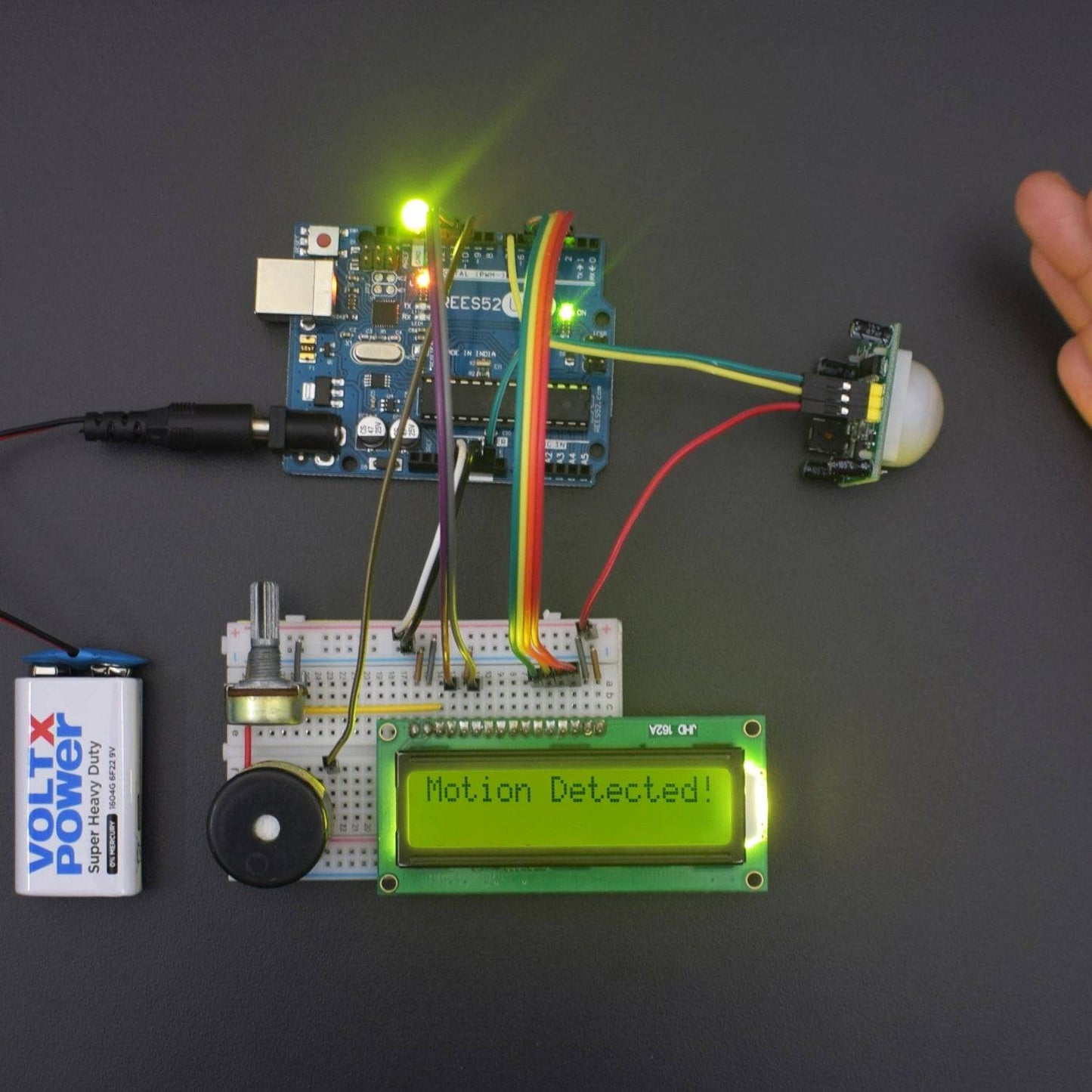
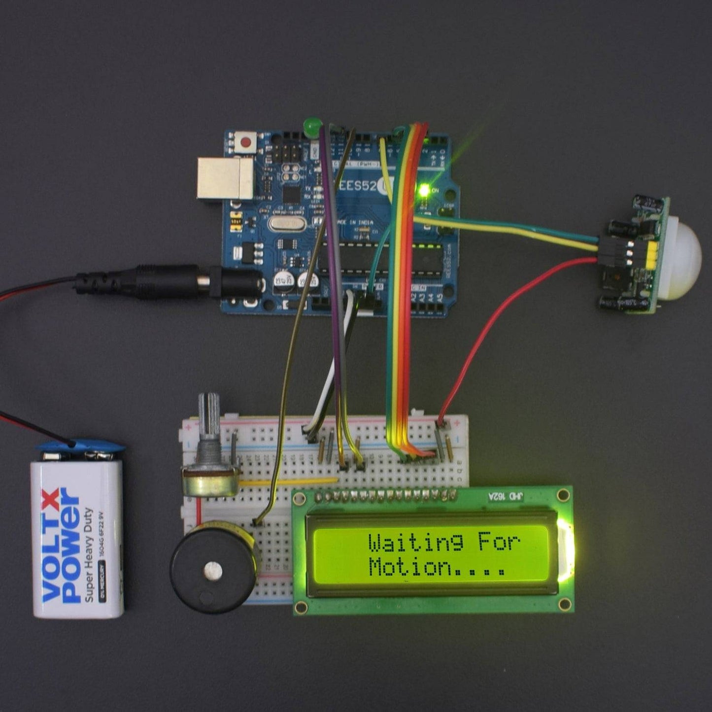
WORKING
When the motion detects by the motion sensor, data will be process and circuit will be completed and buzzer starts playing. Processing will be shown on LCD display.
All the body generate some heat energy in the form of infrared which is invisible to human eyes. But, It can be detected by the electronic sensor. These type of sensor is made up of crystalline material that is Pyroelectric. In this project, we are using the P.I.R. Motion Sensor Module as an infrared sensor that generates the electric charge when exposed in heat and sends a signal to Arduino. According to the level of the infrared in front of the sensor, Arduino displays the status on L.C.D and start buzzing speaker and glows the L.E.D.A simple program is running on Arduino which checks the sensor if anything is moved or new object has been detected.