


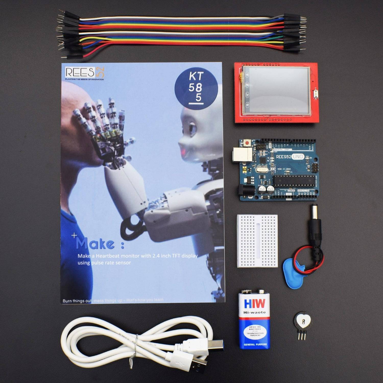


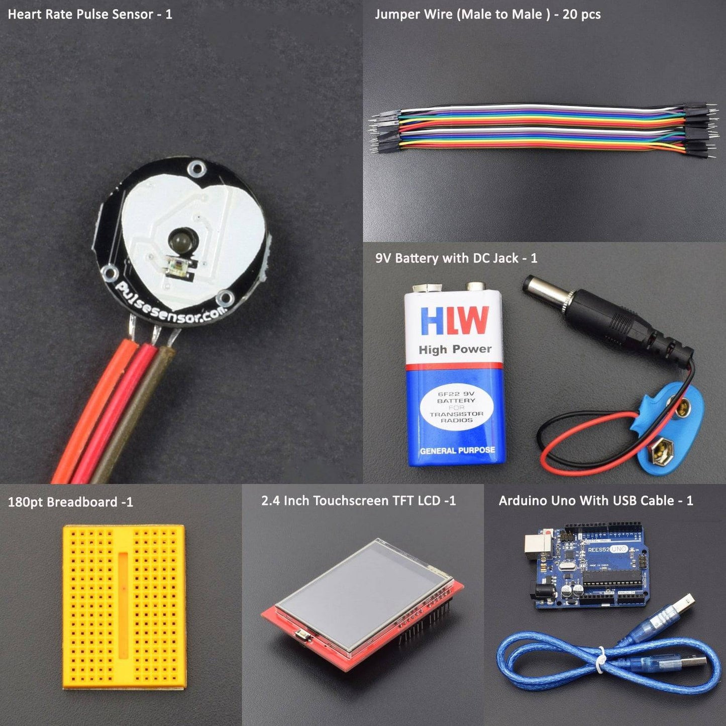

- Arduino Uno with USB Cable – 1
- 2.4-inch TFT display touchscreen shield - 1
- Heart rate Sensor Module – 1
- 9v Battery - 1
- Snapper with DC jack -1
- Breadboard 170 point -1
- Jumper wire (Male to Male)- 20 pc
Introduction
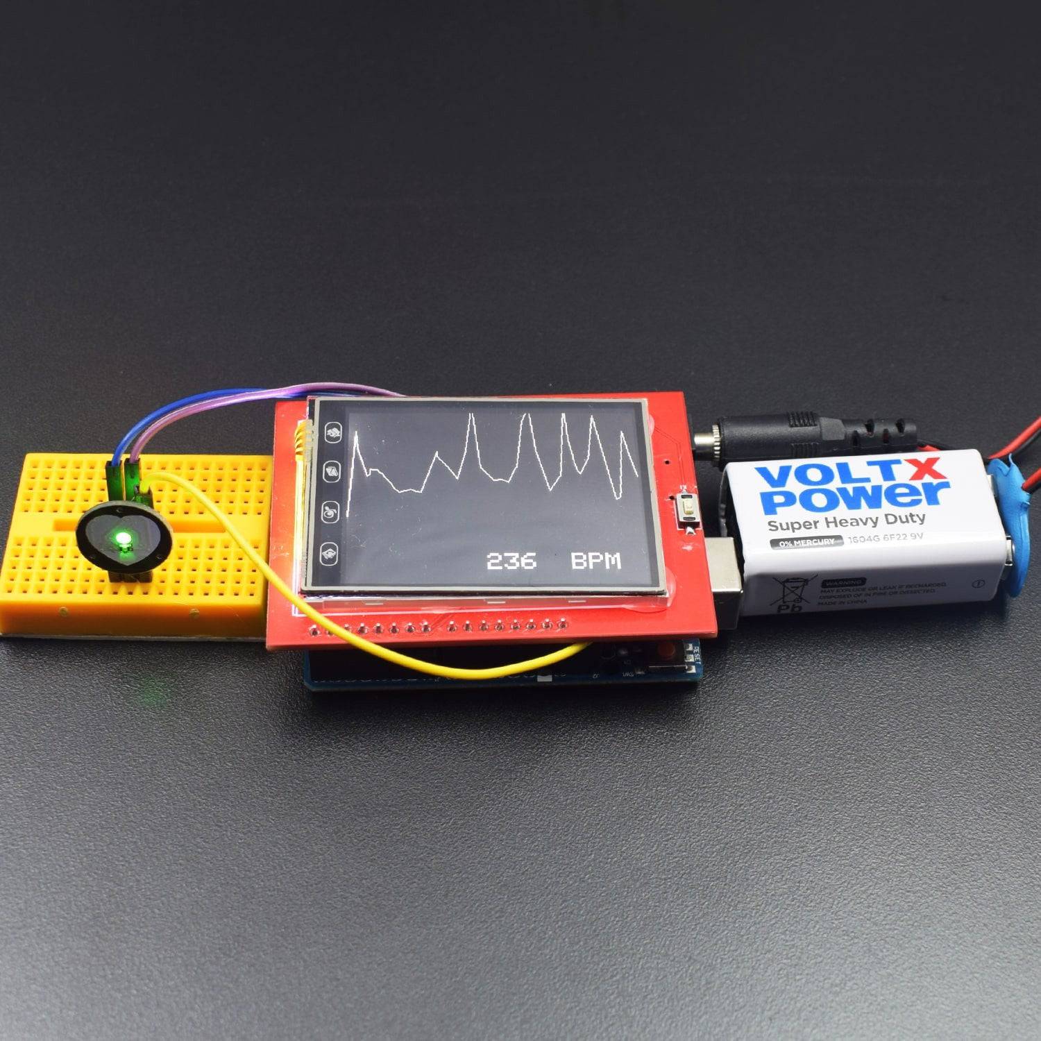
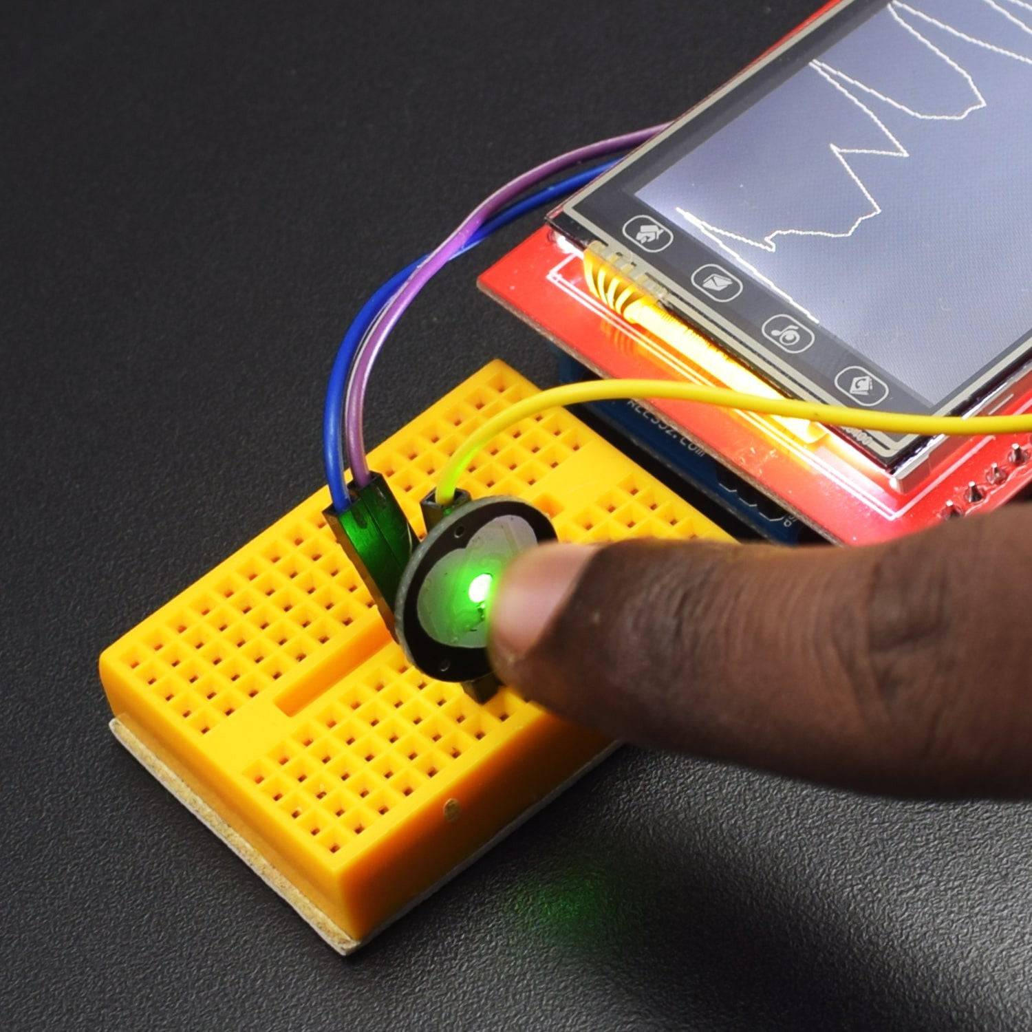
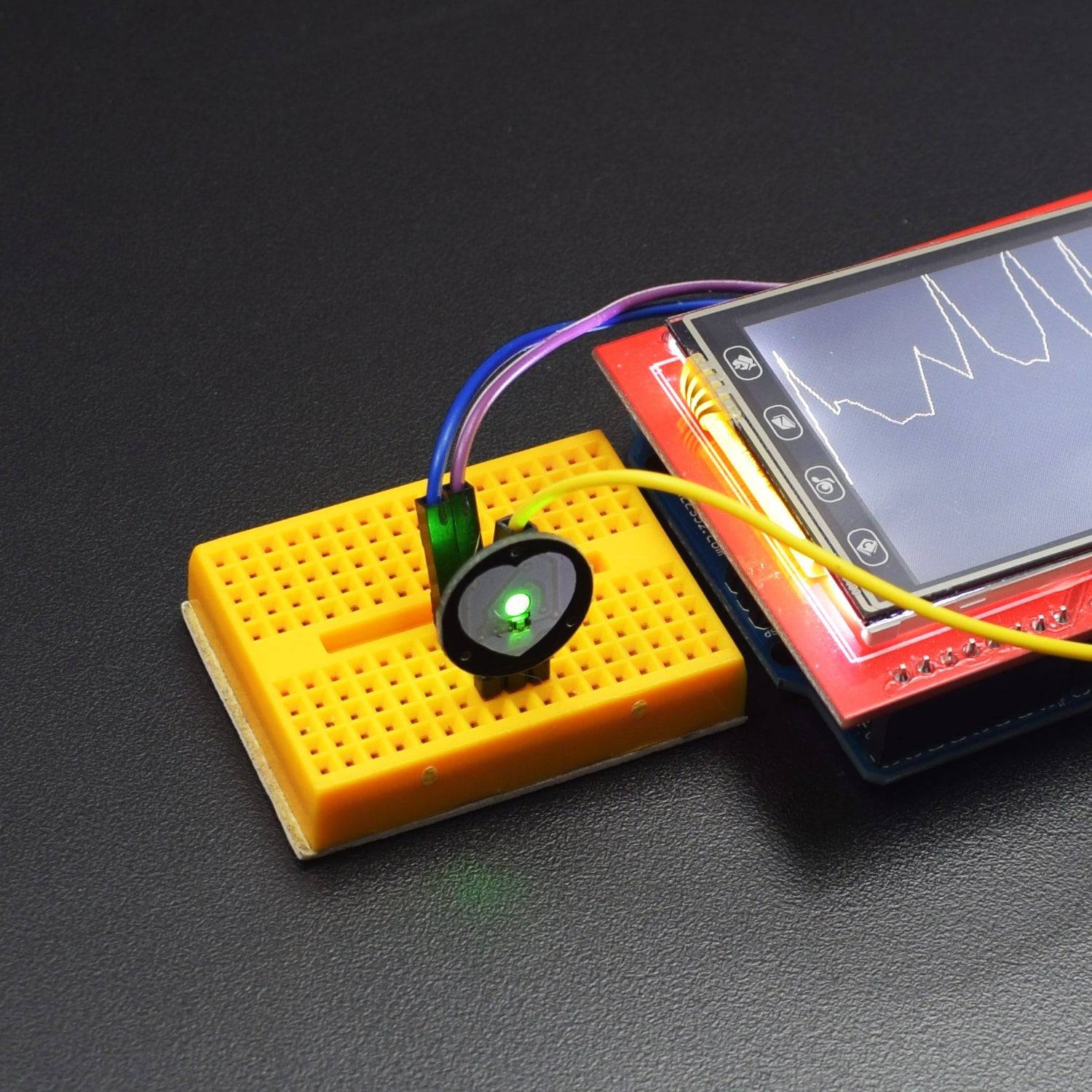
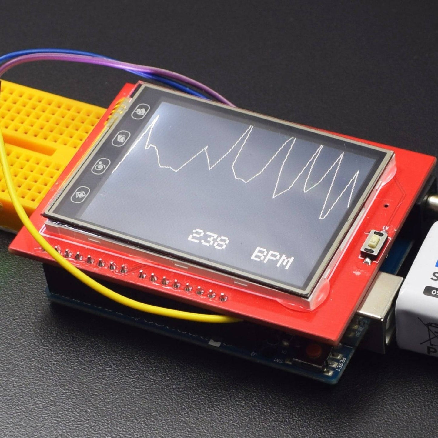
In this project, we have used the 2.8inch TFT screen to display the heart rate graph of a person as measured by the heart rate sensor.
HARDWARE REQUIRED
- Arduino Uno with USB Cable – 1
- 2.4-inch TFT display touchscreen shield - 1
- Heart rate Sensor Module – 1
- 9v Battery - 1
- Snapper with DC jack -1
- Breadboard 170 point -1
- Jumper wire (Male to Male)- 20 pc
SOFTWARE REQUIRED
Arduino IDE 1.8.5 (programmable platform for Arduino)
Click To Download: https://www.arduino.cc/en/Main/Software
SPECIFICATIONS
2.4 TFT Display
This 2.4” TFT Touchscreen is designed to suitable for Arduino UNO/Mega2560. It can directly plug into the UNO/Mega2560 board without any wiring and soldering. Library is compatible with Adafruit TFT touchscreen shield, which is easy to use.

- 2.4" diagonal LCD TFT display
- 240x320 resolution
- ILI9341 controller with built-in video RAM buffer
- Works with any Arduino '328 or Mega
- 5V compatible! Use with 3.3V or 5V logic
- with white LED backlight.
- Support Mini SD card extension
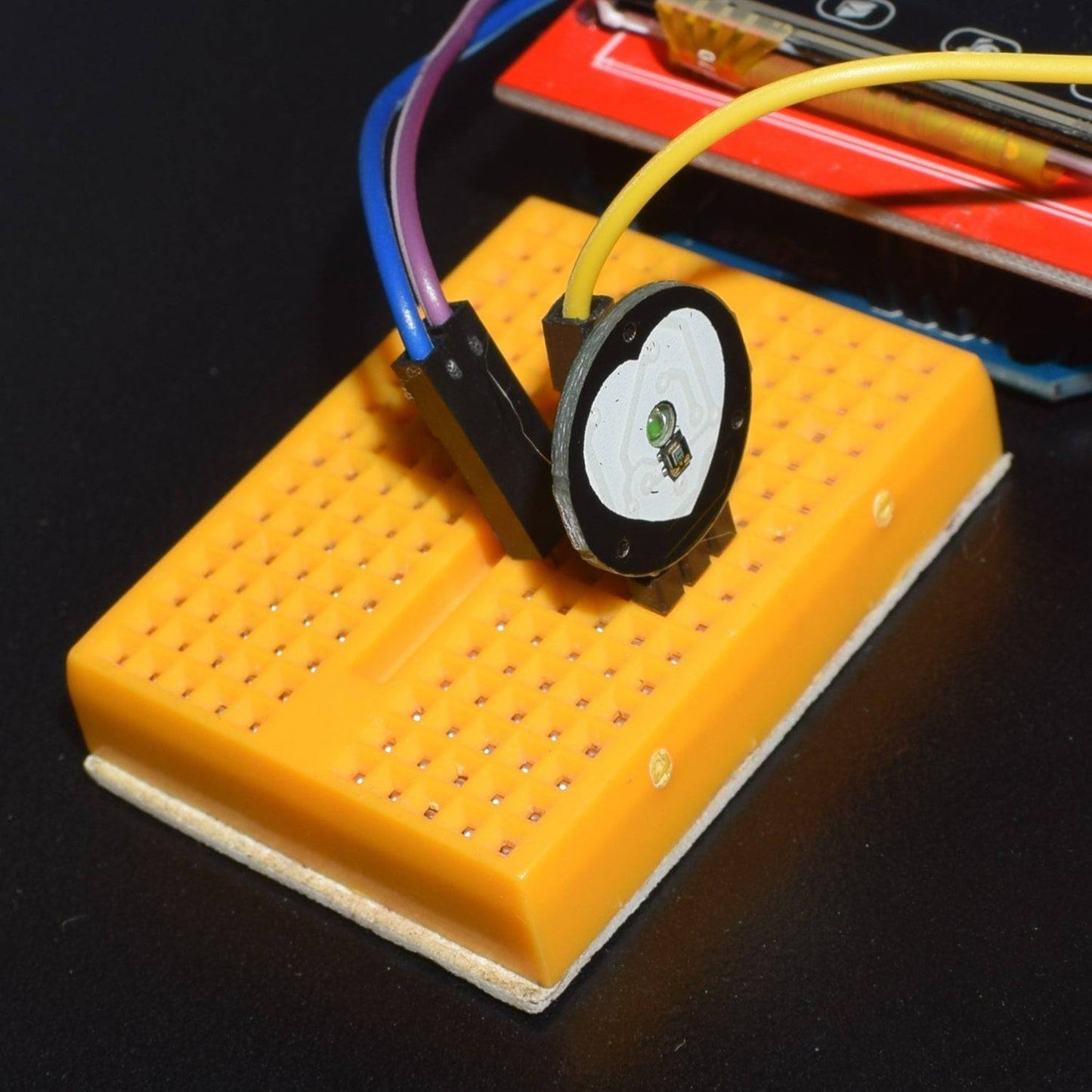
Heart Rate Sensor Module

- Biometric Pulse Rate or Heart Rate detecting sensor
- Plug and Play type sensor
- Operating Voltage: +5V or +3.3V
- Current Consumption: 4mA
- Inbuilt Amplification and Noise cancellation circuit.
- Diameter: 0.625”
- Thickness: 0.125” Thick
Warning:This sensor is not a medical or FDA approved. It is purely intended for hobby projects/demos and should not be used for health critical applications.
Pin Number |
Pin Name |
Wire Colour |
Description |
1 |
Ground |
Black |
Connected to the ground of the system |
2 |
Vcc |
Red |
Connect to +5V or +3.3V supply voltage |
3 |
Signal |
Purple |
Pulsating output signal. |
LIBRARY REQUIRED
Before uploading the code, Must install this library:
Adafruit_GFX.h
https://github.com/adafruit/Adafruit-GFX-Library
Adafruit_TFTLCD.h
https://github.com/adafruit/TFTLCD-Library
- Open the Arduino IDE software
- On Arduino IDE >> Sketch >> Include Library >> Manage Libraries >> search for Adafruit tft lcd library then install, and search for Adafruit_GFX then install this Library.

CIRCUIT CONNECTION

- Firstly cut two male to male jumper wires from one end and remove the insulation.
- Connect one wire to the 5V supply on arduino with the other side on positive (+) pin of the heart rate sensor.
- Similarly connect negative (-) pin of sensor to GND of arduino.
- Connect the S pin on sensor to pin SCL on arduino and bend it.
(SDK pin is the pin after the pin 13 and SCL pin is next to it).
- Now gently mount the TFT screen shield on the arduino uno without removing the two wires without insulation
CODE
Click to see code here:
https://drive.google.com/open?id=1SzM1ubMq5EMET49_xhwRB8sEo3wryCeM
WORKING AND OUTPUT
Welcome to the Arduino Based project which consists of heart rate sensor module that gives an analog output which is converted into beats per minute in the code and the resultant graph of the bpm is displayed on the TFT screen.
The heart rate is monitored every second.

Click to watch the tutorial
For more tutorials subscribe our channel REES52 on YouTube