


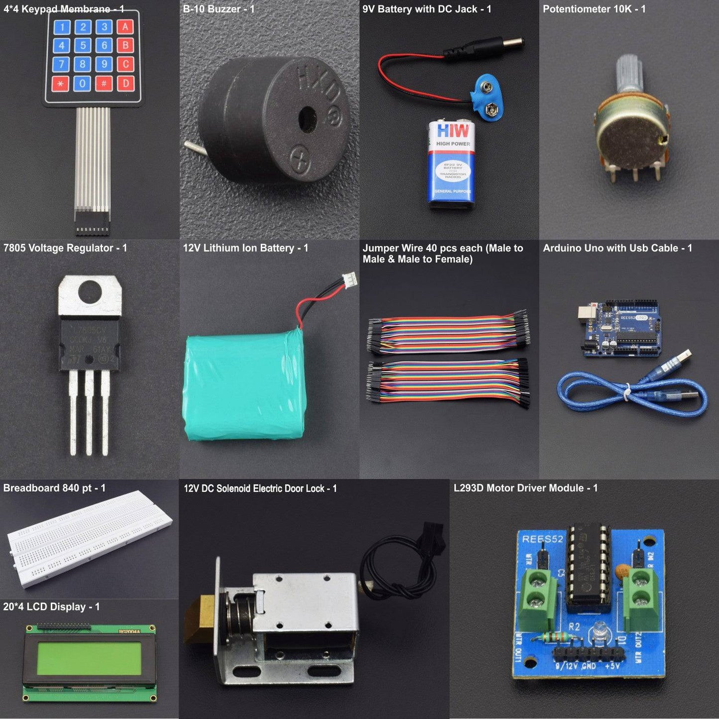


KIT INCLUDES:
- 20*4 LCD Display - 1
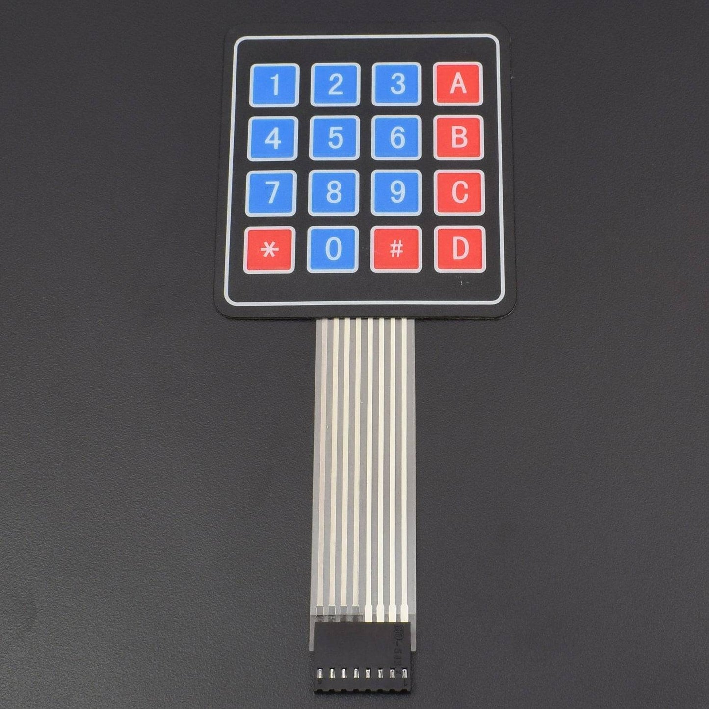
- 4x4 Keypad Membrane - 1
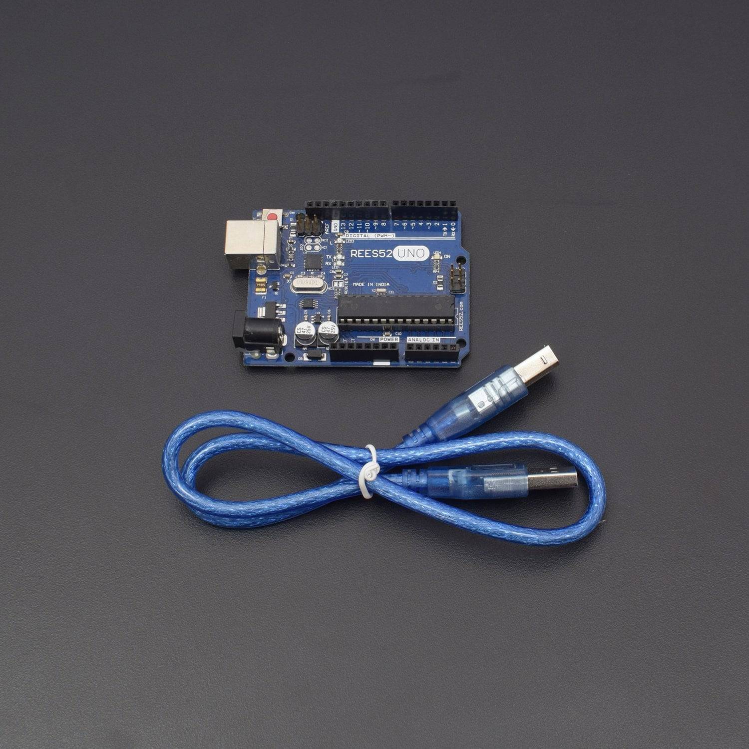
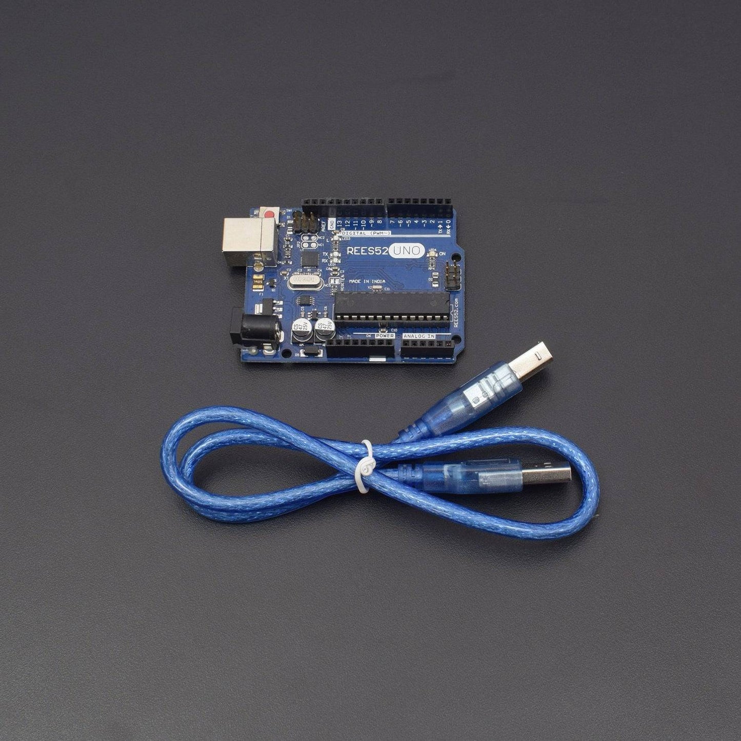
- Arduino UNO with USB Cable - 1
- Buzzer B10 - 1
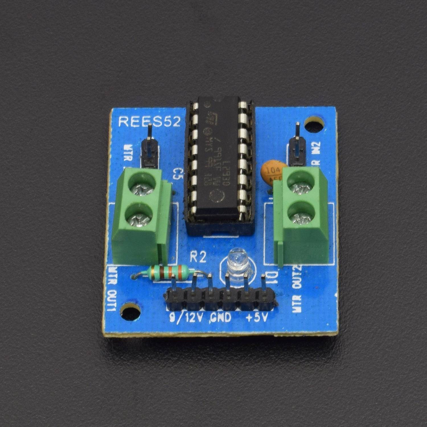
- DC Motor Driver L293D – 1
- 12v DC Door Lock Solenoid – 1
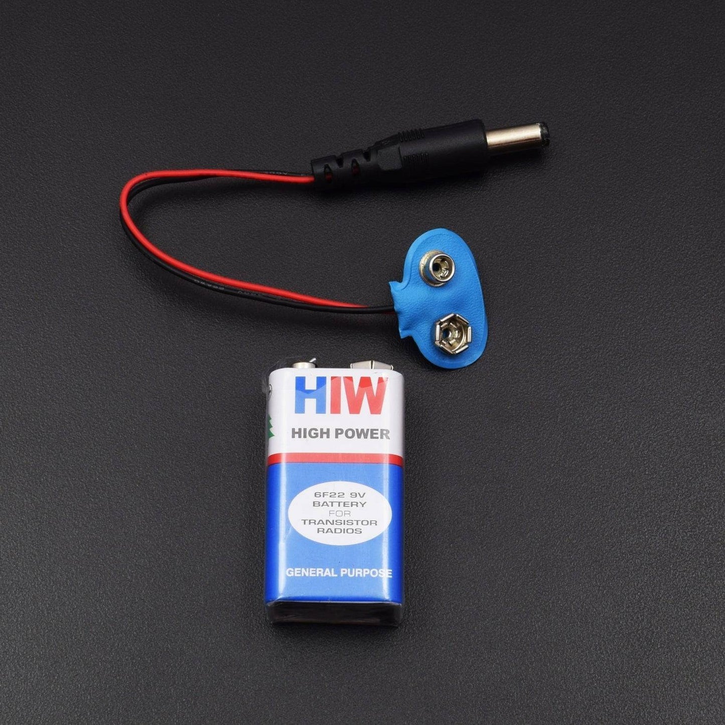
- 9v Battery with DC jack – 1
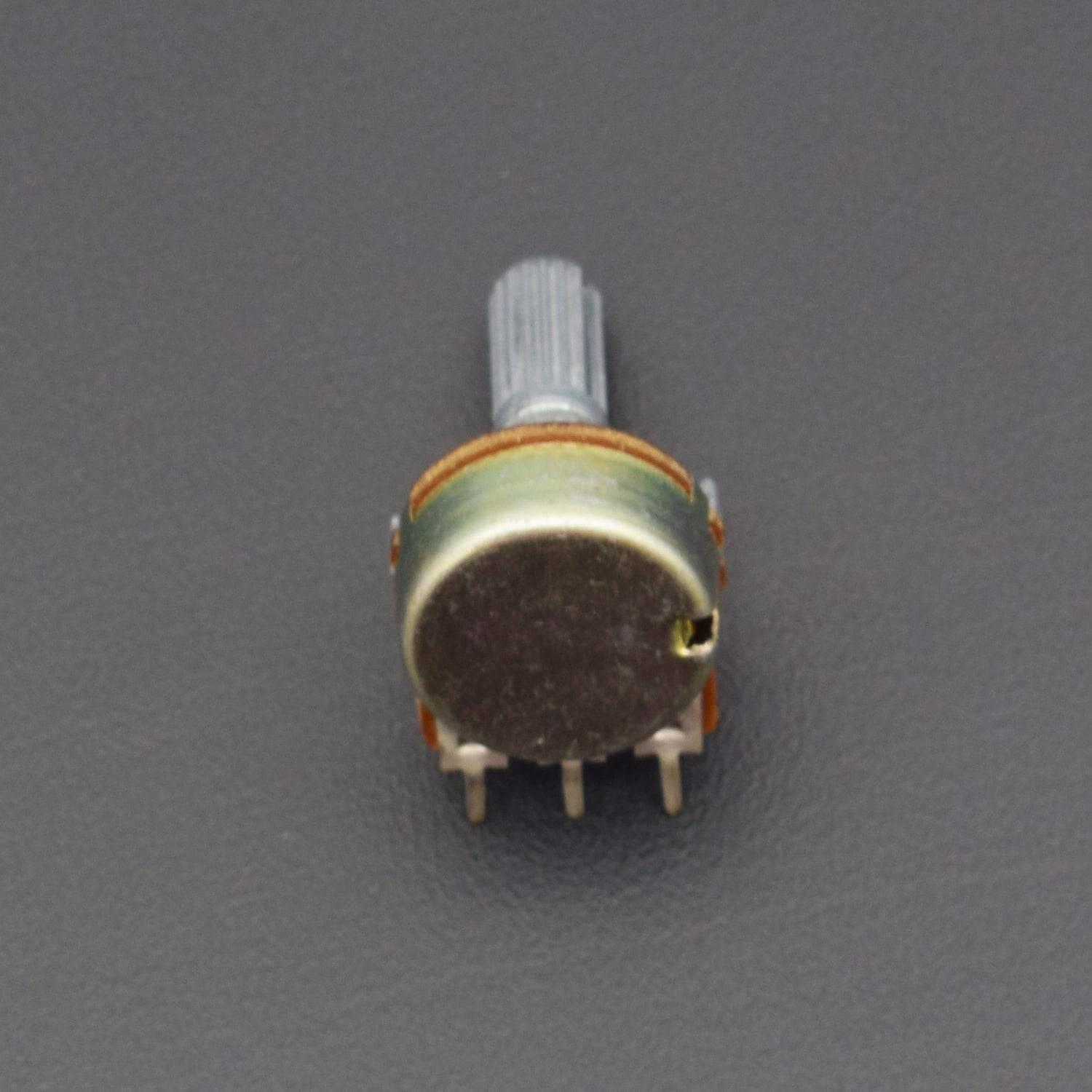
- Potentiometer 10 k – 1
- 7805 Voltage regulator - 1
- 12v lithium ion battery – 1
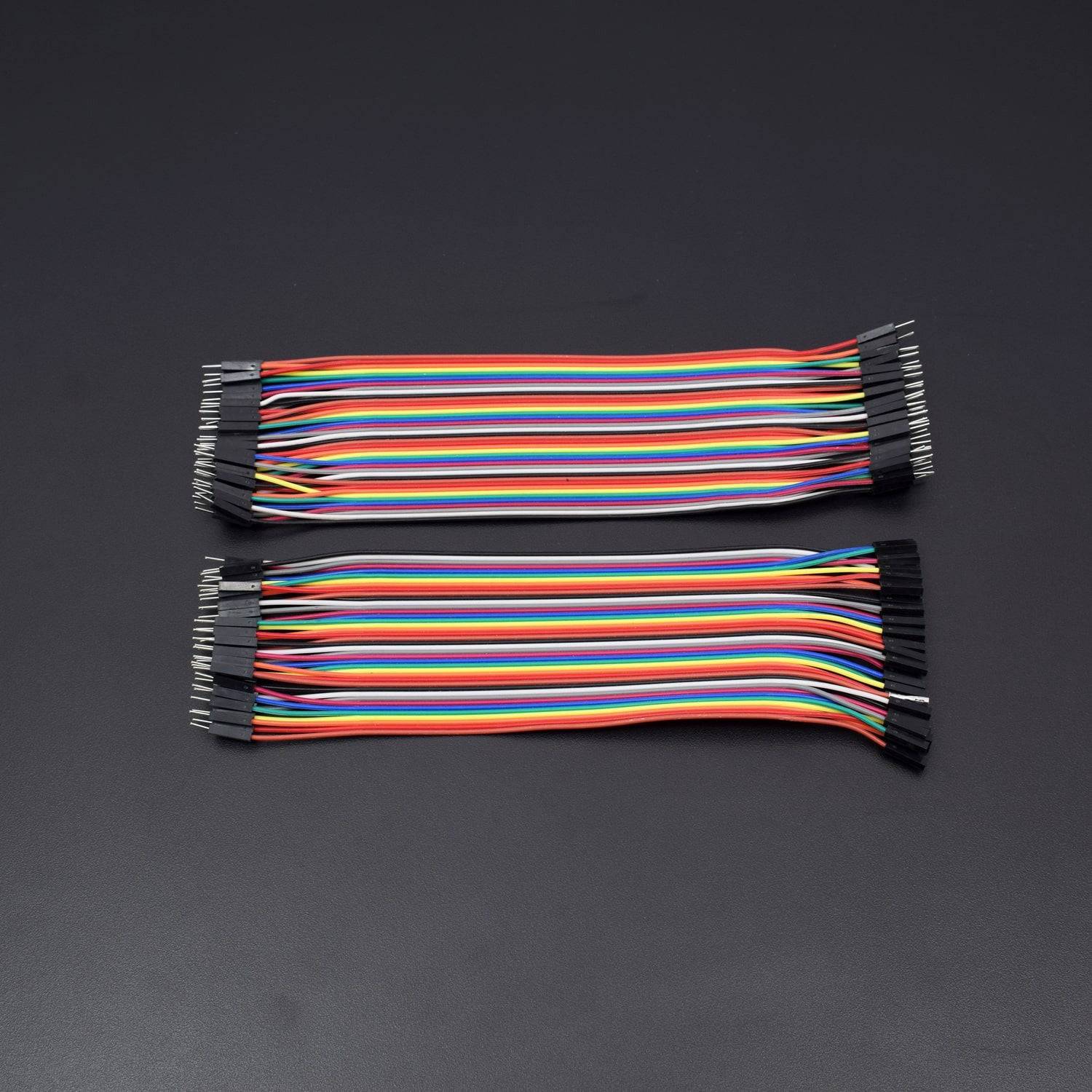
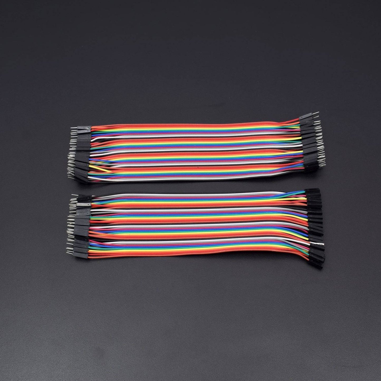
- Jumper wires male to female – 40 pieces
- Jumper wires male to male – 40 pieces
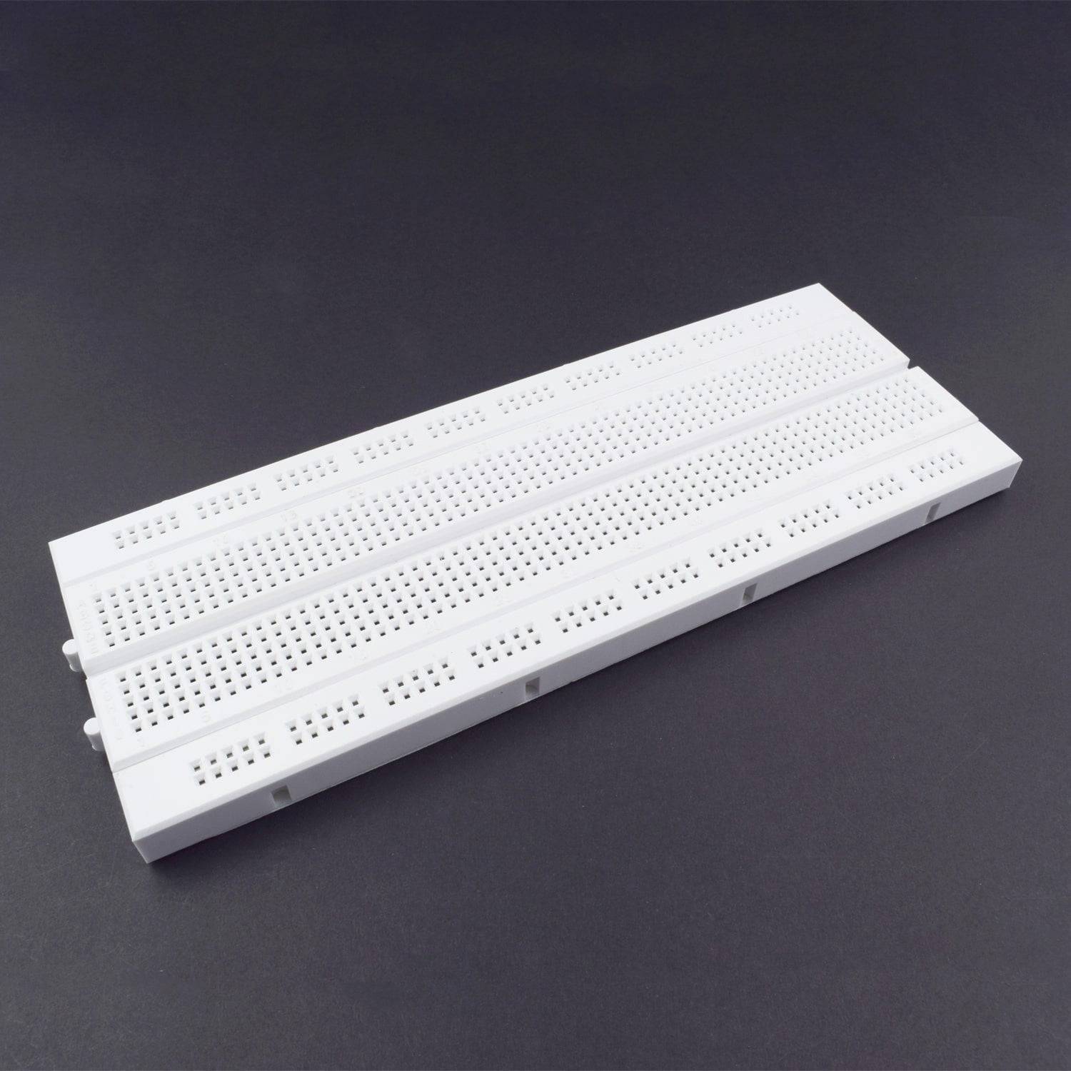
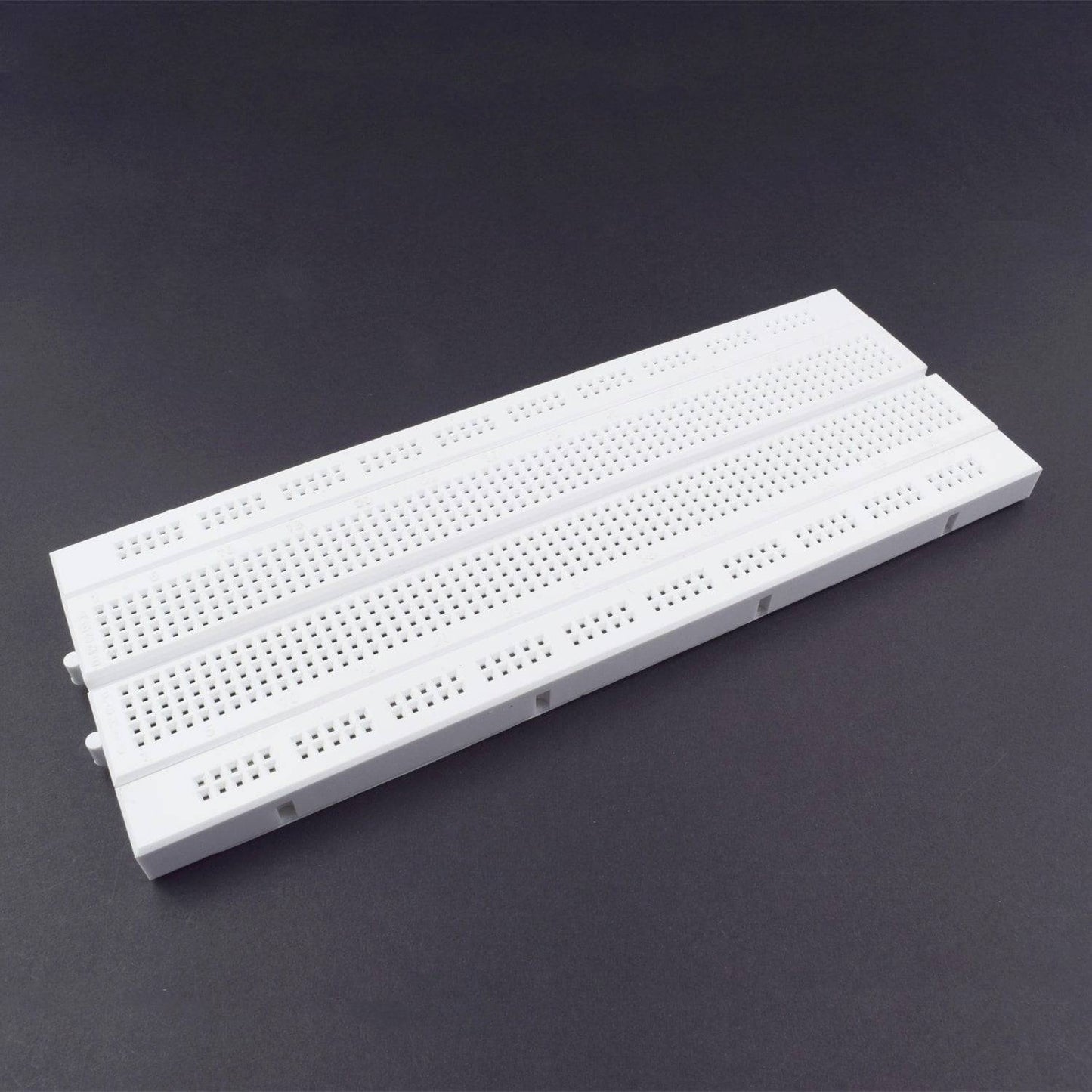
- Breadboard 840 points – 1
HARDWARE REQUIRED
- 20*4 LCD Display - 1
- 4x4 Keypad Membrane - 1
- Arduino UNO with USB Cable - 1
- Buzzer B10 - 1
- DC Motor Driver L293D – 1
- 12v DC Door Lock Solenoid – 1
- 9v Battery with DC jack – 1
- Potentiometer 10 k – 1
- 7805 Voltage regulator - 1
- 12v lithium ion battery – 1
- Jumper wires male to female – 40 pieces
- Jumper wires male to male – 40 pieces
- Breadboard 840 points – 1
- SOFTWARE REQUIRED
Arduino IDE 1.8.5 (programmable platform for Arduino)
Click To Download :https://www.arduino.cc/en/Main/Software
SPECIFICATIONS
20*4 LCD Display
- LCD Display Mode: STN, Positive, Transflective
- Display Colour: Deep Blue/ Yellow Green
- Viewing Angle: 6H
- Driving Method: 1/16 duty, 1/5 bias
- Back Light: Yellow-Green LED backlight
- Outline Dimension: 803615.8 MAX
Note |
|
4*4 Keypad membrane
- Maximum Rating: 24 VDC, 30 mA
- Interface: 8-pin access to 4x4 matrix
- Operating temperature: 32 to 122 °F(0 to 50°C)
- Dimensions: Keypad, 2.7 x 3.0 in (6.9 x 7.6 cm),Cable: 0.78 x 3.5 in (2.0 x 8.8 cm)
PIN DESCRIPTION
20*4 LCD Display
Symbol |
External Connection |
Function |
VSS |
Power Supply |
Signal GROUND for lcm |
VDD |
POWER SUPPLY for logic lcm |
|
V0 |
Contrast Adjust |
|
RS |
MPU |
Register Select Signal |
RW |
MPU |
Read/Write Select Signal |
E |
MPU |
Operation Enable Signal |
DB0~DB3 |
MPU |
Four Low order bidirectional three state bus lines. Used for data transfer between the MPU and LCM. These four are not used between 4 Bit operations. |
DB4~DB7 |
MPU |
Four high order bidirectional Three state bus lines used for data transfer between the MPU |
A |
LED BKL power Supply |
Power Supply for BKL |
K |
4*4 Keypad Membrane
Matrix keypads use a combination of four rows and four columns to provide button states to the host device, typically a microcontroller. Underneath each key is a pushbutton, with one end connected to one row, and the other end connected to one column.
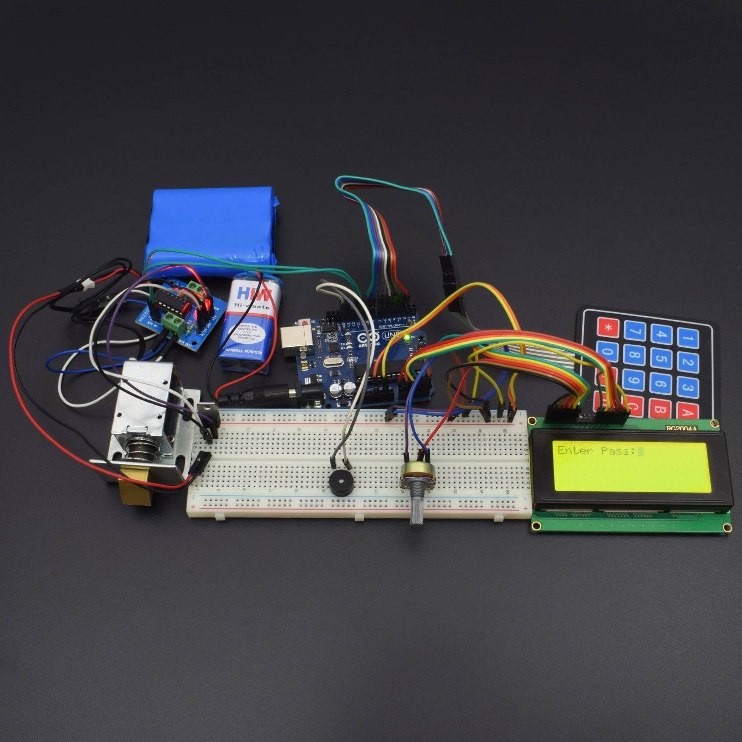
CIRCUIT CONNECTION
The Digital Pins 2 to 9 are connected to the 4x4 Keypad. Pin A0 to A5 are used to control the 16x2 LCD Display. Pin 11 and 12 are connected to the input unit of motor driver L293D and the output unit of motor driver is connected to the Door Lock Assembly. Similarly, pin 13 is connected to the positive terminal of Buzzer.
The entire circuit is powered by using a 12V DC Adapter, however, we may need to use a voltage regulator IC (LM 7805) to convert 12V DC to 5V DC as Arduino UNO is working in 5V DC.

CODE
Upload the below-given Sketch to Arduino UNO. Makesure to include keypad.h and Password.h libraries to your Arduino IDE before uploading the Sketch to Arduino UNO. These two libraries are not coming default with Arduino IDE Software.
You can download them from below links:
Click here(http://www.arduino.cc/playground/uploads/Code/Keypad.zip) to download the Keypad Library
Click here(http://www.arduino.cc/playground/uploads/Code/Password.zip) to download the Password Library
These files will be downloaded in Zip format. You can import them to Arduino IDE by Going: Sketch --> Import Library --> Add Library and Navigate to download location. Once the libraries are successfully added to Arduino IDE. Now you can upload the below Sketch to your Arduino UNO.
WORKING
16x2 LCD Display: LCD (Liquid Crystal Display) screen is an electronic display module and find a wide range of applications. A 16x2 LCD display is very basic module and is very commonly used in various devices and circuits. These modules are preferred over seven segments and other multi segment LEDs. The reasons being: LCDs are economical; easily programmable; have no limitation of displaying special & even custom characters (unlike in seven segments), animations and so on.This block is considered as the Output unit. Arduino will be interacting to user by sending messages and instruction using this section.
4x4 Keypad: This block is considered as the input unit. Users will be interacting to the circuit by using this section. This 16-button keypad provides a useful human interface component for microcontroller projects. User will be using this keypad to Type password for unlocking the door and Locking the door again.
Arduino UNO: The ArduinoUno is a microcontroller board based on the ATmega328. It has 14 digital input/output pins (of which 6 can b e used as PWM outputs), 6 analog inputs, a 16 MHz ceramic resonator, a USB connection, a power jack, an ICSP header, and a reset button. It contains everything needed to support the microcontroller; simply connect it to a computer with a USB cable or power it with an AC - to - DC adapter or battery to get started
Arduino UNO will be controlling and coordinating all the components that is connected to this project.
Buzzer: This is an electrical device that makes a buzzing noise. We are using this device to provide Keypad tone, Warning tone, Success tone etc.
DC Motor Driver L293D: A Motor Controller is a device that acts as an intermediary between your robot’s microcontroller, batteries and motors. A motor controller is necessary because a microcontroller can usually only provide roughly 0.1 Amps of current whereas most actuators (DC motors, DC gear motors, servo motors etc.) require several Amps.
Door Lock Assembly: This is actually a mechanical assembly which is controlled by a DC motor that is associated with it. This Assembly will be locking and unlocking the Door. But Arduino can control this assembly by controlling the DC motor that is associated with it.