


Description:
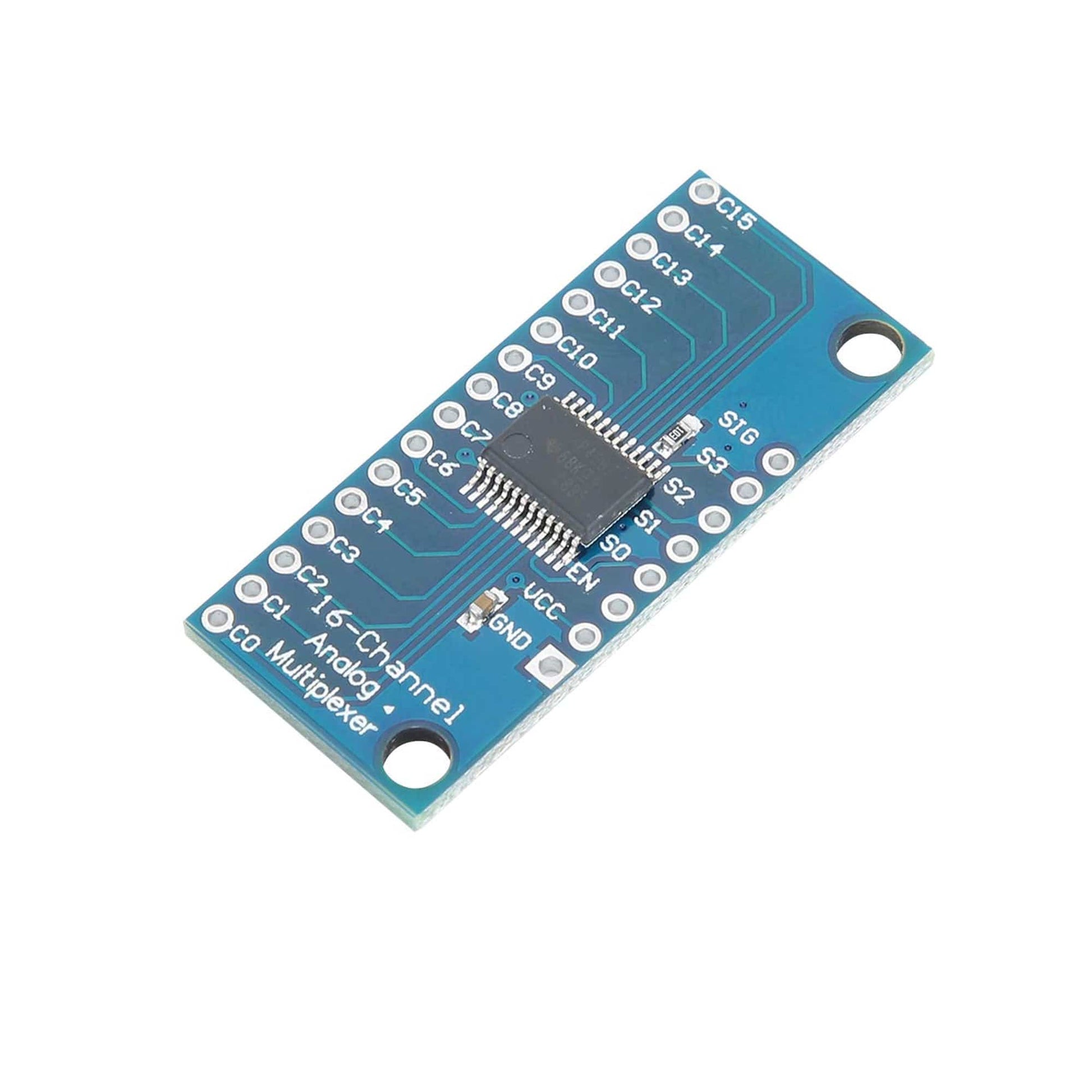
This is a CD74HC4067 16-Channel Multiplexer breakout board that mounts a 74HC4067 which is a 16-channel Analog multiplexer/demultiplexer that can route both analog and digital signals in both directions. 1 of 16 input channels can be routed to 1 output or 1 input can be routed to 1 of 16 output channels.
CD74HC4067 16-Channel Multiplexer can handle analog signals such as from analog sensors or a bank of potentiometers or CD74HC4067 16-Channel Multiplexer can handle digital signals such as from switches, digital sensors or even serial communications. The 74HC4067 can operate over the range of 2 to 6V, so CD74HC4067 16-Channel Multiplexer is compatible with both 3.3 and 5V logic.
CD74HC4067 16-Channel Multiplexer uses binary addressing, so address 0000 is Channel 0, address 1111 is Channel 15. When a channel is ON, CD74HC4067 16-Channel Multiplexer has a resistance of about 70 ohms which allows signals to flow both ways. Maximum current is 25mA through any of the channels.
Specifications:
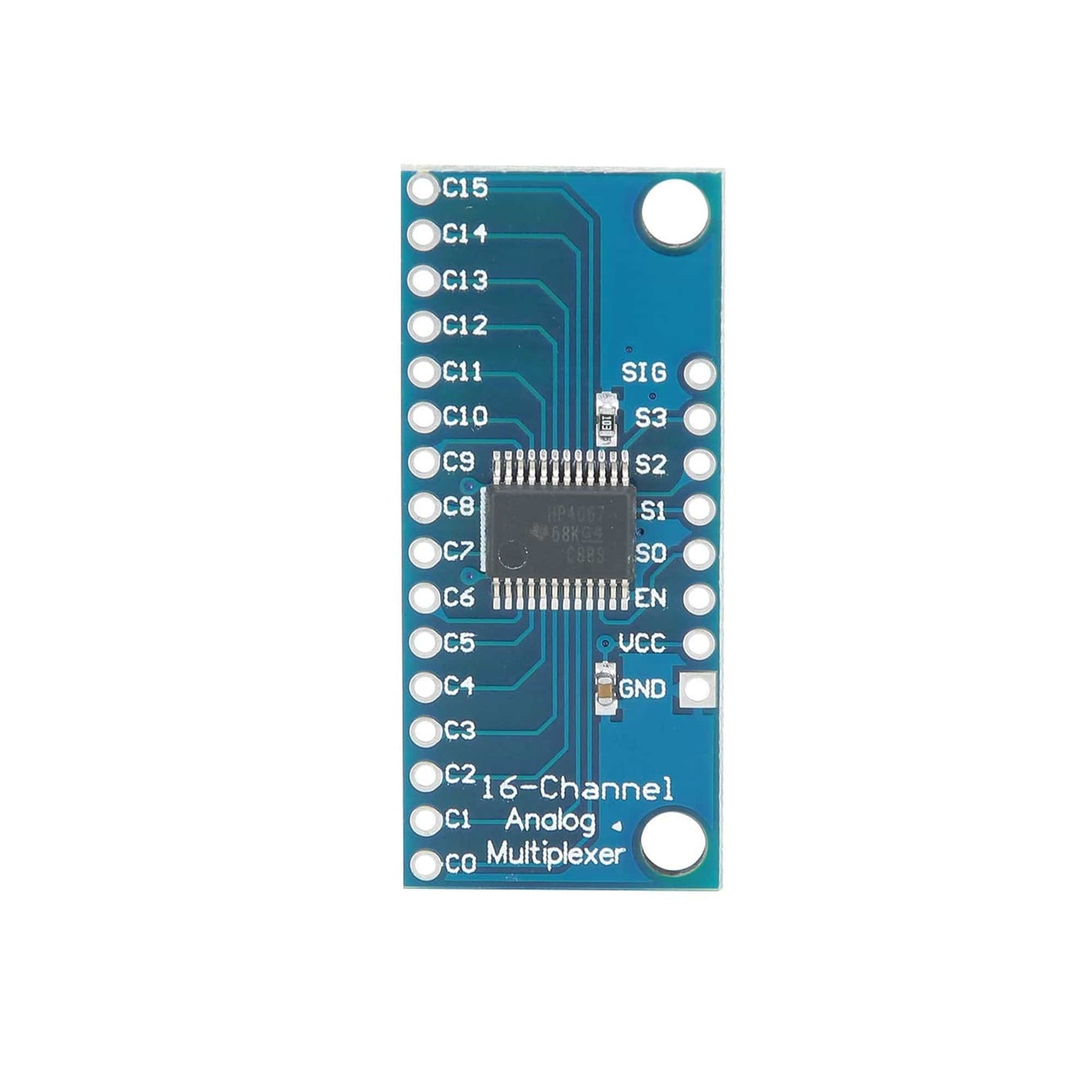
- Chipset: CD74HC4067
- Channels: 16
- Address Lines: 4
- Supply: 2V to 6V
- On resistance: 70 Ohms @ 4.5V
- 6ns break-before-make @ 4.5V
- Temperature Range: -55C to 125C
Pin Description:
- 1×8 Header Location
- SIG = Signal Input / Output. This will usually connect to an analog input or digital I/O on the microcontroller
- S3 = Binary Address Bit 3. The address bits (3…0) connect to 4 digital output pins on the microcontroller to select channel.
- S2 = Binary Address Bit 2
- S1 = Binary Address Bit 1
- S0 = Binary Address Bit 0
- EN = Enable. Internally pulled LOW to enable by default. Can be pulled HIGH to disable all channels.
- VCC = 2 to 6V. Usually connected to 5V or 3.3V to match the microcontroller power.
- GND = Ground, must be common with the microcontroller.
- 1×16 Header Location
- C15 = Channel 15
- C0 = Channel 0
Package Included:
1 x CD74HC4067 16-Channel Multiplexer CD74HC4067 16-Channel Analog Digital Multiplexer Breakout Board Module for Arduino