


REES52
Make an IoT based Temperature Level Indicator using LEDs and DHT11 Module with ESP8266-12e Wi-Fi Board compatible with Arduino Uno - KT569
Make an IoT based Temperature Level Indicator using LEDs and DHT11 Module with ESP8266-12e Wi-Fi Board compatible with Arduino Uno - KT569
SKU:KT569
50 in stock
Regular price
Rs. 799.00
Regular price
Sale price
Rs. 799.00
Shipping calculated at checkout.
Quantity
Couldn't load pickup availability
- For Bulk Order Click Here
- Need Customer Support?
- Free Delivery Above 999/-
For refund/return/replacement, call us at +91 95995 94520 , +91 95991 22209 or mail us at support@rees52.com
Delivery Time
Delivery Time
- Delivery time with the Express Shipping option is 2-3 working days, and with the Standard Shipping option is 5-6 working days. It varies based on location, reliant on courier services.
- Delivery time if the order item is on Preorder Status is 15-20 working days.
COD (Cash on Delivery)
COD (Cash on Delivery)
- For COD you have to pay extra charges of Rs 350/- before the shipment. (We will share the company QR Code, UPI ID or Account details for the same)


INTRODUCTION
In this project, we will design an IOT-based temperature level indicator using a DHT11 Temperature and humidity sensor module and an LED in which the Temperature level will be shown on the LED according to the Temperature value.
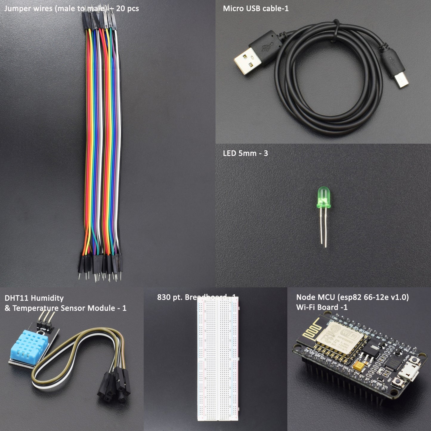
HARDWARE REQUIRED
- Node MCU (esp82 66-12e v1.0) Wi-Fi Board -1pc
- NodeMcu USB Cable - 1pc
- DHT11 Module -1pc
- Jumper Wires (male to male) – 20 pcs
- 830 pt. Breadboard - 1pc
- Led 5mm-3pcs
SOFTWARE REQUIRED
Arduino IDE 1.8.10 (programmable platform for Arduino)
Click here to download the software

SPECIFICATIONS
NodeMCU ESP8266 CP2102 Module:
- ESP8266 CP2102 NodeMCU LUA ESP-12E WIFI Serial Wireless Module
- Built-in Micro-USB, with flash and reset switches, easy to program
- Full I/O port and Wireless 802.11 supported, direct download, no need to reset
- Arduino compatible works great with the latest Arduino IDE/Mongoose IoT/Micro Python

DHT11 Module:
- Operating Voltage: 3.5v to 5.5v
- Operating current: 0.3mA (measuring) 60uA (standby)
- Output: Serial data
- Temperature Range: 0°C to 50°C
- Humidity Range: 20% to 90%
- Resolution: Temperature and Humidity both are 16-bit
- Accuracy: ±1°C and ±1%

|
1 |
Vcc |
Power supply 3.5V to 5.5V |
|
2 |
Data |
Outputs both Temperature and Humidity through serial Data |
|
3 |
Ground |
Connected to the ground of the circuit |
LIBRARY REQUIRED
- DHT11 - Click to open 👈
- Adafruit Sensor Library - Click to open 👈
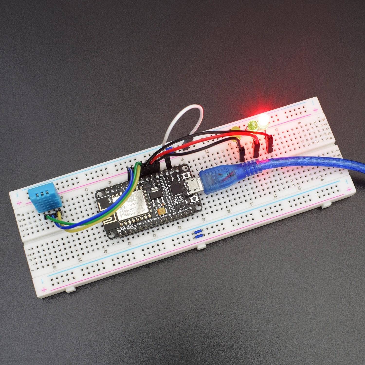
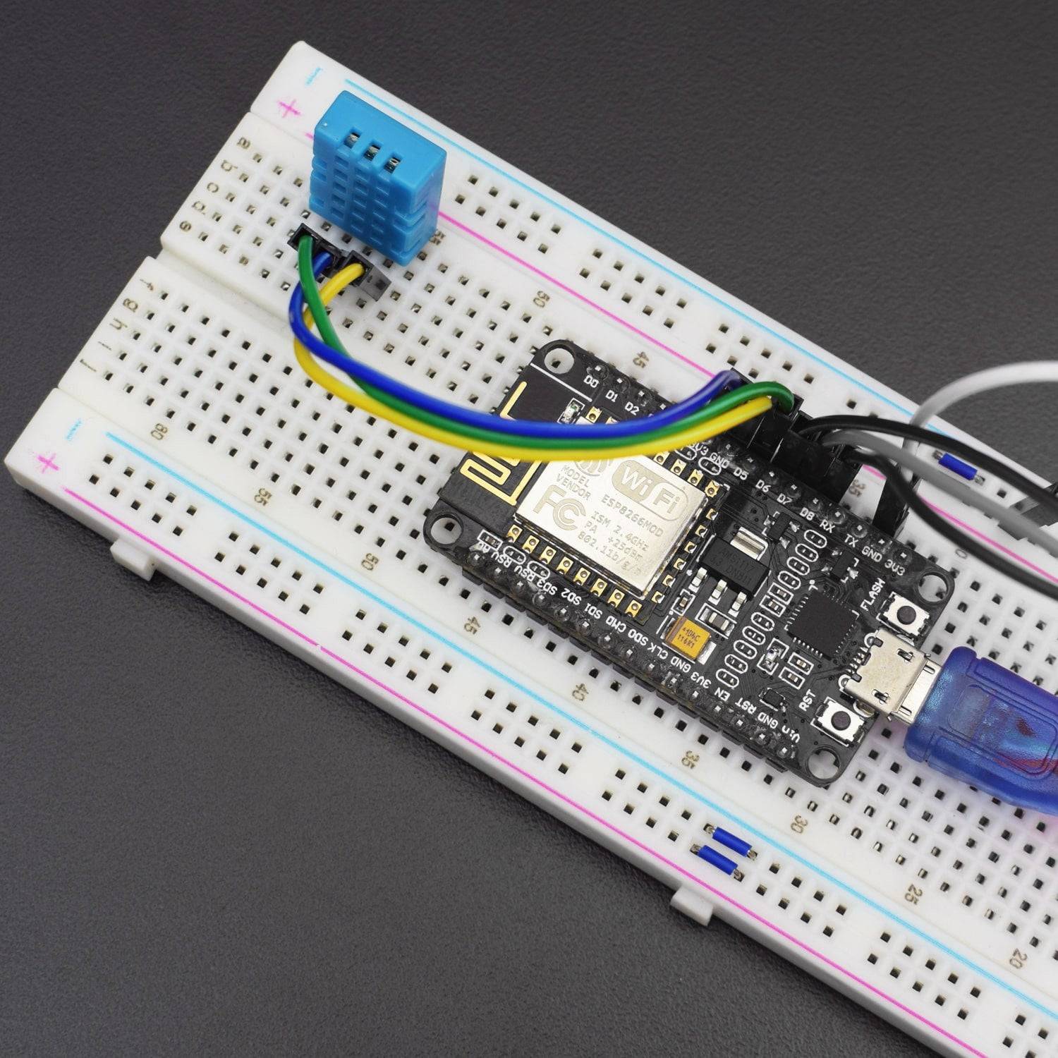
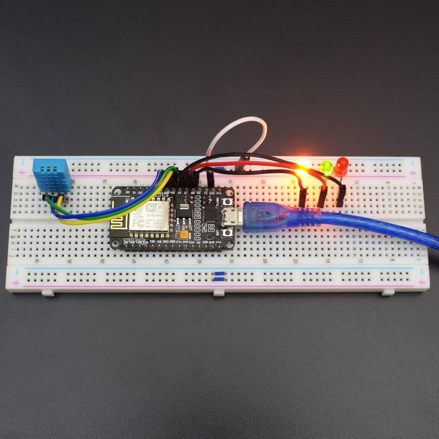
CIRCUIT CONNECTION
- Connect the “S” pin of the DHT11 module to pin D5 of the NodeMCU ESP8266-12e board.
- Connect the “V” pin of the DHT11 module to the pin 3v3 NodeMCU ESP8266-12e board.
- Connect the ground pin of the DHT11 module to the ground pin of the NodeMCU ESP8266-12e board.
- Connect the positive leg of LED1 to the D8 pin of NodeMCU ESP8266-12e board.
- Connect the positive leg of LED2 to the D7 pin of NodeMCU ESP8266-12e board.
- Connect the positive leg of LED3 to the D6 pin of NodeMCU ESP8266-12e board.
- Connect the GND leg of all LEDs to the GND rail on the breadboard.

CODE
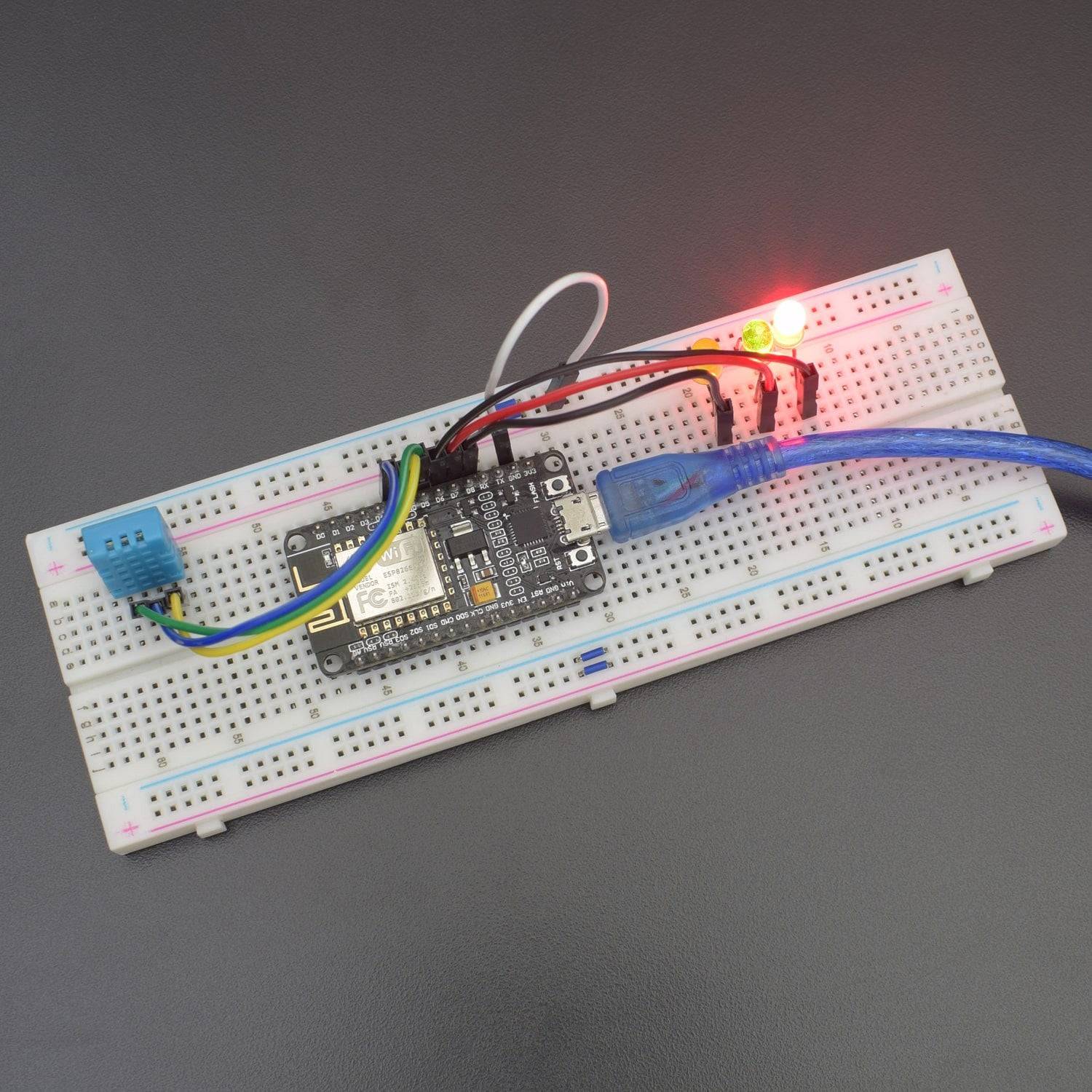
WORKING AND OUTPUT
Welcome to the Node MCU-based project.
- As the 3 LED are connected, the first LED will get ON when the temperature rises greater than 20.
- The 2nd LED will get ON when the temperature is between 20 to 27.
- The 3rd LED will get ON when the temperature rises more than 29. And the Buzzer get ON indicates “TOO HOT”.