KIT INCLUDES :
- Resistors (10K – 5 & 470 ohm - 5)
- Capacitor 100 µf – 5
- Breadboard 830 pt. – 1
- Transistor BC547 - 5
- Single stand wire 2mt – 1
- Led 5 mm – 8
- 9v Battery - 1
- Battery snapper – 1
Introduction
In this video we will make a 5 led chaser circuit using BC547 transistor and capacitors.
All transistors are BC547 are used in this circuit can be replaced by 2N222 transistor. You can use capacitors between 10-100 µf and resistors between 10k to 50k.
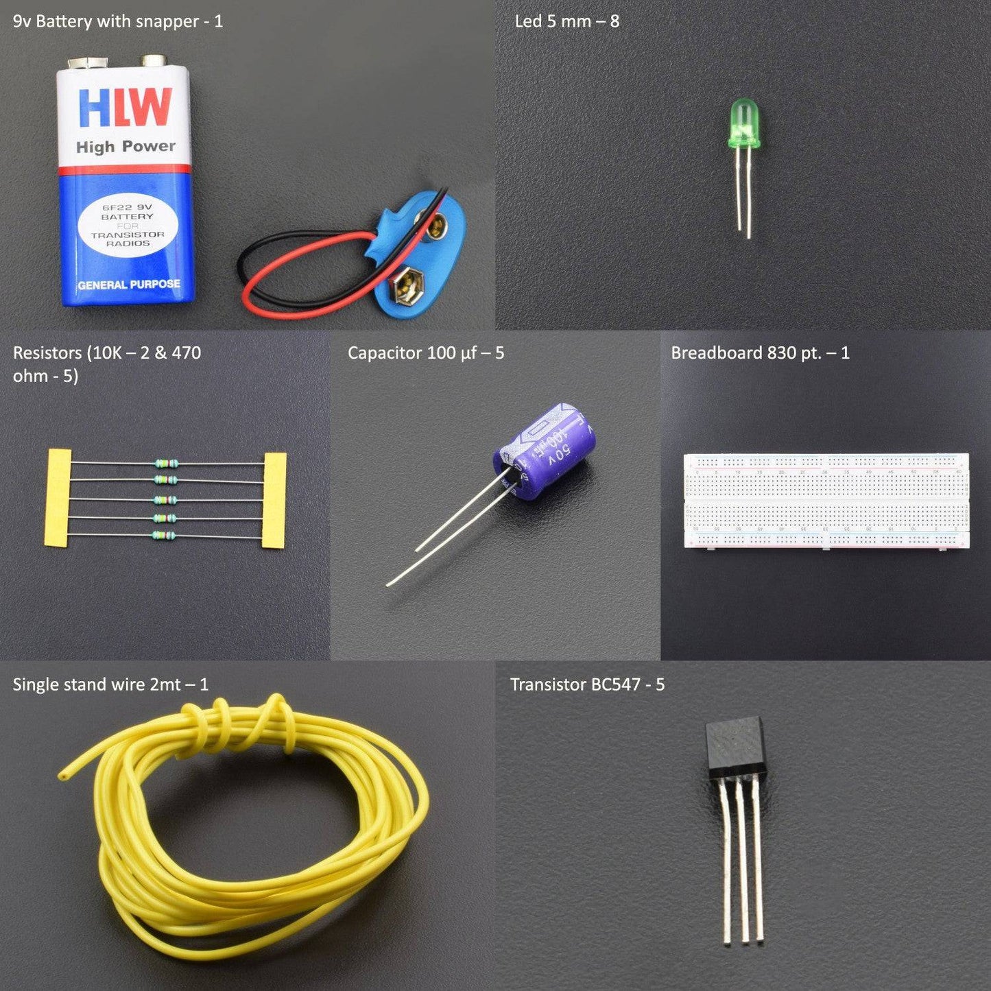
HARDWARE REQUIRED
- Resistors (10K – 5 & 470 ohm - 5)
- Capacitor 100 µf – 5
- Breadboard 830 pt. – 1
- Transistor BC547 - 5
- Single stand wire 2mt – 1
- Led 5 mm – 8
- 9v Battery - 1
- Battery snapper – 1
SPECIFICATIONS
Led

Capacitor

BC547 Transistor
![]()
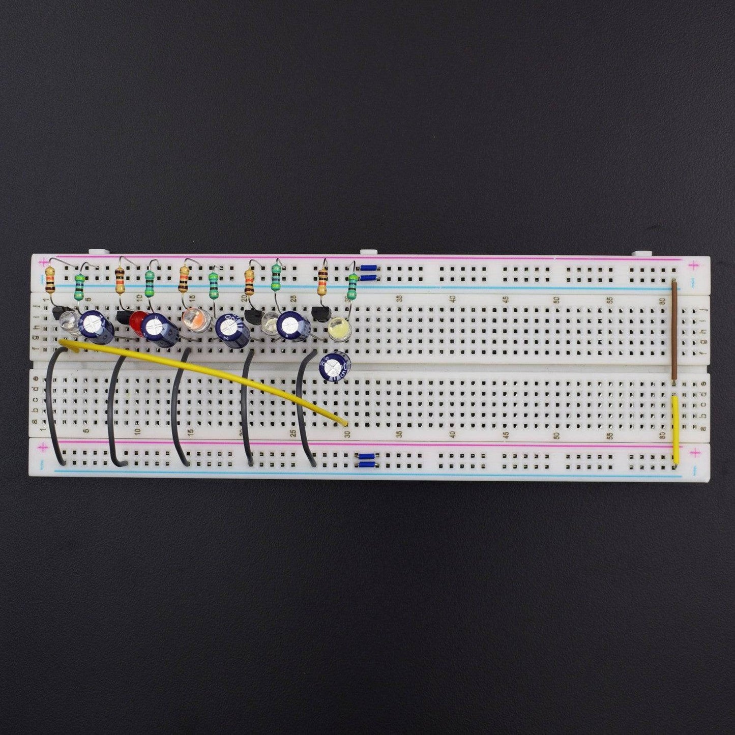
CIRCUIT CONNECTION
- Attach all the transistor to the breadboard
- Connect Base pin of all transistors to the positive rail via 10k resistor.
- Connect cathode pin of leds to the collector pin of each transistor
- Connect anode of leds to the positive rail on the breadboard via 470-ohm resistor.
- Connect emitter of each Transistor to negative rail on the breadboard.
- Connect anode of capacitor to collector of first transistor and cathode of capacitor to base of the second transistor
- Connect similarly all the capacitor with transistor.
- Connect anode of last capacitor to the collector pin of last transistor and cathode of capacitor to Base of the first Transistor.

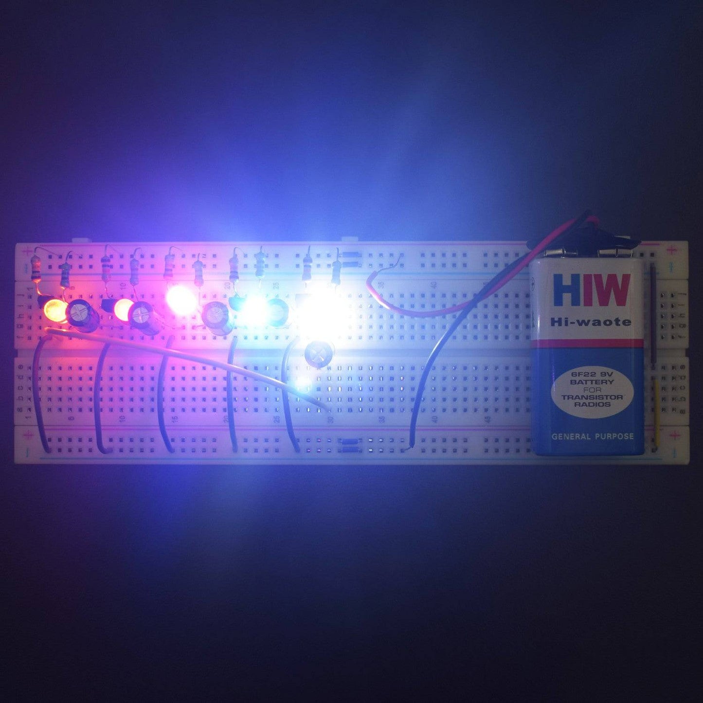
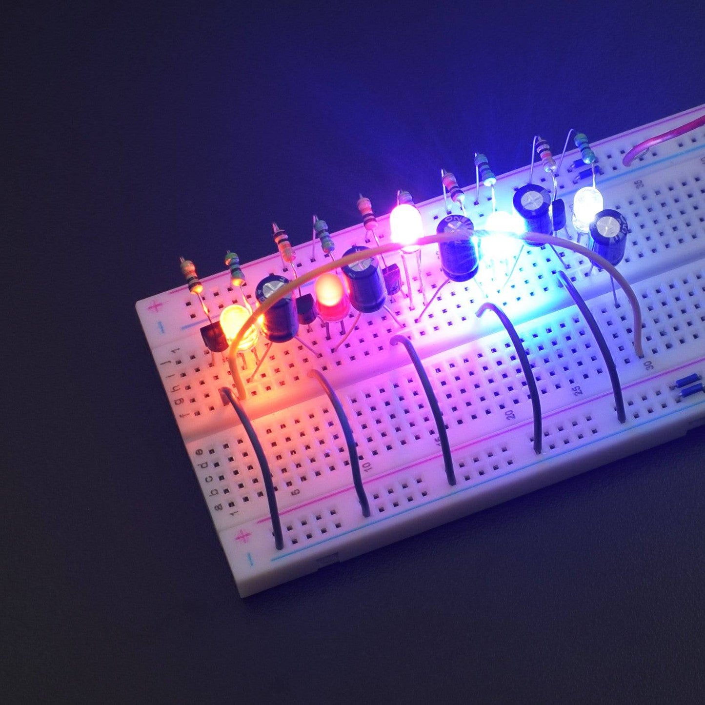
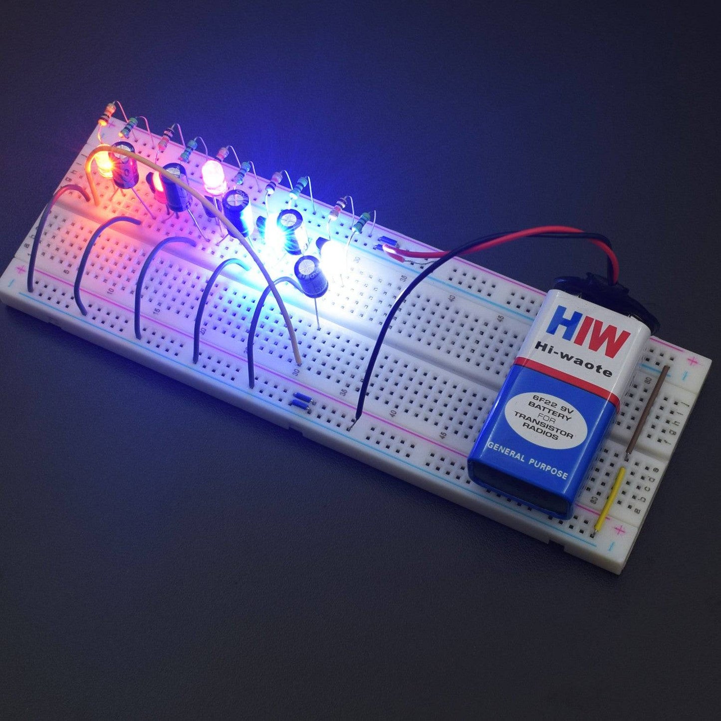
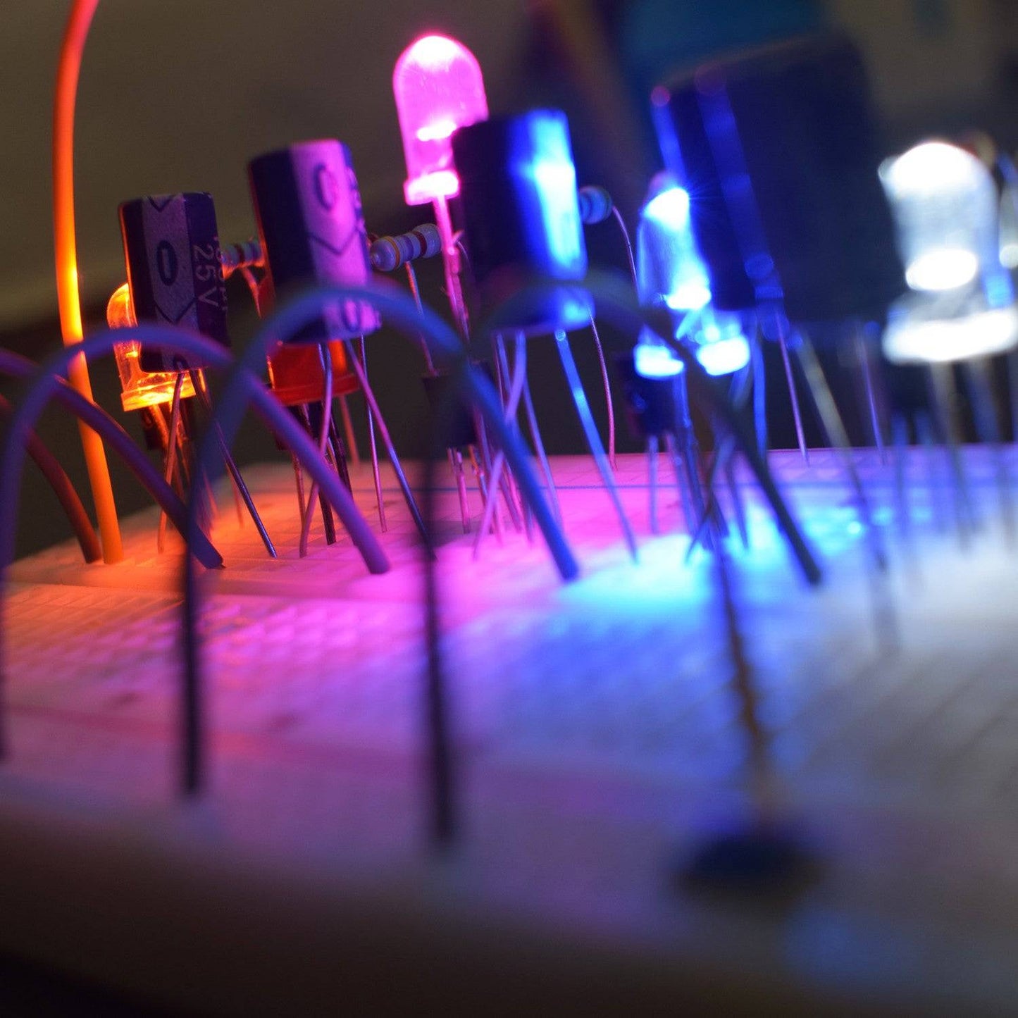
WORKING AND OUTPUT
After connecting the battery, you can see the chasing effect on all the leds.
NOTE:
You can adjust the rate of blinking and chasing by increasing and decreasing capacitor’s and resistor’s value which is connected at the base of the Transistor.

Click to watch the tutorial
For more tutorials subscribe our channel REES52 on YouTube