


REES52
Make an IOT LDR Alarm Circuit Using LDR Module and NodeMCU ESP8266-12E Wi-Fi Module compatible with Arduino Uno - KT571
Make an IOT LDR Alarm Circuit Using LDR Module and NodeMCU ESP8266-12E Wi-Fi Module compatible with Arduino Uno - KT571
SKU:KT571
50 in stock
Couldn't load pickup availability
- For Bulk Order Click Here
- Need Customer Support?
- Free Delivery Above 999/-
For refund/return/replacement, call us at +91 95995 94520 , +91 95991 22209 or mail us at support@rees52.com
Delivery Time
Delivery Time
- Delivery time with the Express Shipping option is 2-3 working days, and with the Standard Shipping option is 5-6 working days. It varies based on location, reliant on courier services.
- Delivery time if the order item is on Preorder Status is 15-20 working days.
COD (Cash on Delivery)
COD (Cash on Delivery)
- For COD you have to pay extra charges of Rs 350/- before the shipment. (We will share the company QR Code, UPI ID or Account details for the same)
INTRODUCTION
In this project, we will design an IOT-based LDR alarm circuit using Node MCU ESP8266-12E Wi-Fi Board and LDR module. When the value exceeds the set value, the alarm will start ringing.
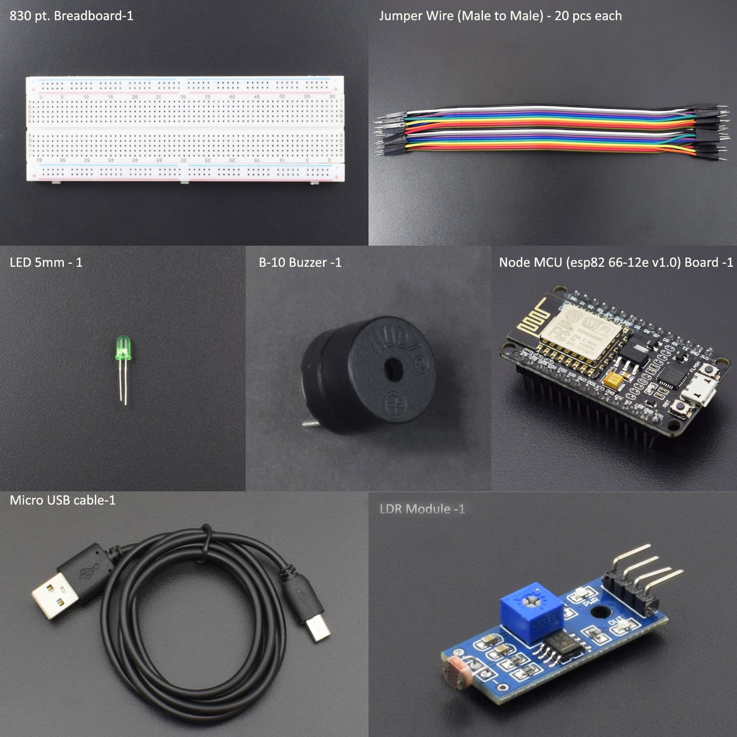
HARDWARE REQUIRED
- Node MCU (esp82 66-12e v1.0) Wi-Fi Board -1pc
- NodeMcu USB Cable - 1pc
- LDR Module -1pc
- Jumper Wires (male to male) – 20 pcs
- 830 pt. Breadboard - 1pc
- B-10 Buzzer - 1pc
- Led 5mm-1pc
SOFTWARE REQUIRED
Arduino IDE 1.8.10 (programmable platform for Arduino)
Click here to download the software

SPECIFICATIONS
NodeMCU ESP8266 CP2102 Wireless Module:
The development board equips the ESP-12E module containing the ESP8266 chip, having a Tensilica Xtensa® 32-bit LX106 RISC microprocessor which operates at 80 to 160 MHz adjustable clock frequency and supports RTOS.
- Operating Voltage: 2.5v to 3.6v
- On-board 3.3V 600mA regulator
- 80mA Operating Current
- 20 µA during Sleep Mode
- ESP8266 CP2102 NodeMCU LUA ESP-12E WIFI Serial Wireless Module
- Built-in Micro-USB, with flash and reset switches, easy to program
- Full I/O port and Wireless 802.11 supported, direct download, no need to reset
- Arduino compatible works great with the latest Arduino IDE/Mongoose IoT/Micro Python

WARNING:
The ESP8266 requires a 3.3v power supply and 3.3v logic levels for communication. The GPIO pins are not 5v-tolerant! You must do some level shifting if you want to interface the board with 5v (or higher) components.
LDR Module:
The Light Dependent Resistor (LDR) is just another special type of Resistor and hence has no polarity
- Operating Voltage: 3.3V to 5V DC
- Operating Current: 15ma
- Output Digital - 0v to 5v, Adjustable trigger level from preset
- Output Analogue - 0v to 5v based on light falling on the LDR
Pin Description:
- VCC = 3.3V to 5V DC
- GND = Ground
- S = Output

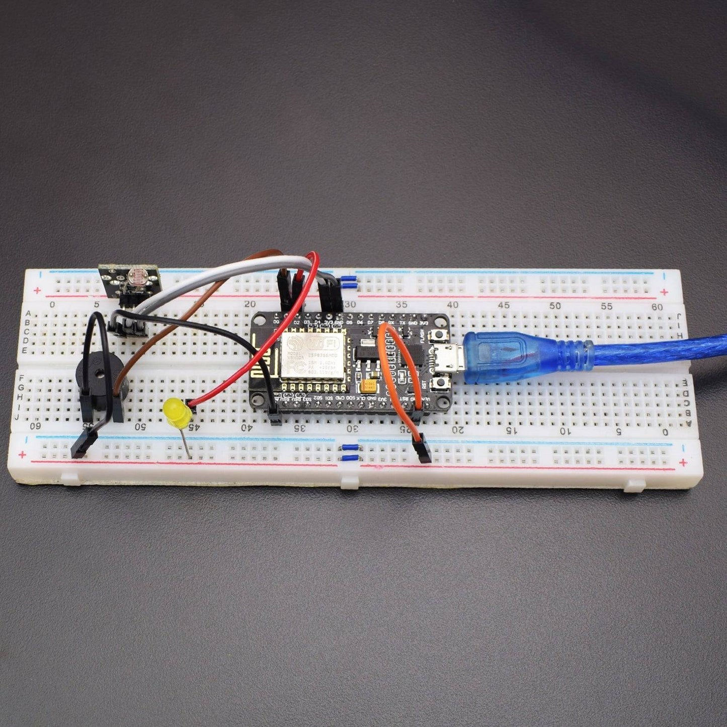
CIRCUIT CONNECTION
- Connect the “A0 (Signal)” pin of the LDR module to the “A0” pin of NodeMCU ESP8266-12e Wi-Fi Module.
- Connect the “GND” pin of the LDR module to GND pin of NodeMCU ESP8266-12e Wi-Fi Module.
- Connect the +5v pin of the LDR module to the 3.3v pin of NodeMCU ESP8266-12e Wi-Fi Module.
- Connect the LED ground pin to the GND pin of the NodeMCU ESP8266-12e Wi-Fi Module.
- Connect LED VCC to D2(GPIO4) pin of NodeMCU ESP8266-12e Wi-Fi Module.
- Connect Buzzer Gnd to Gnd pin of NodeMCU ESP8266-12e Wi-Fi Module.
- Connect Buzzer Positive to D1 (GPIO5) pin of NodeMCU ESP8266-12e Wi-Fi Module.

CODE
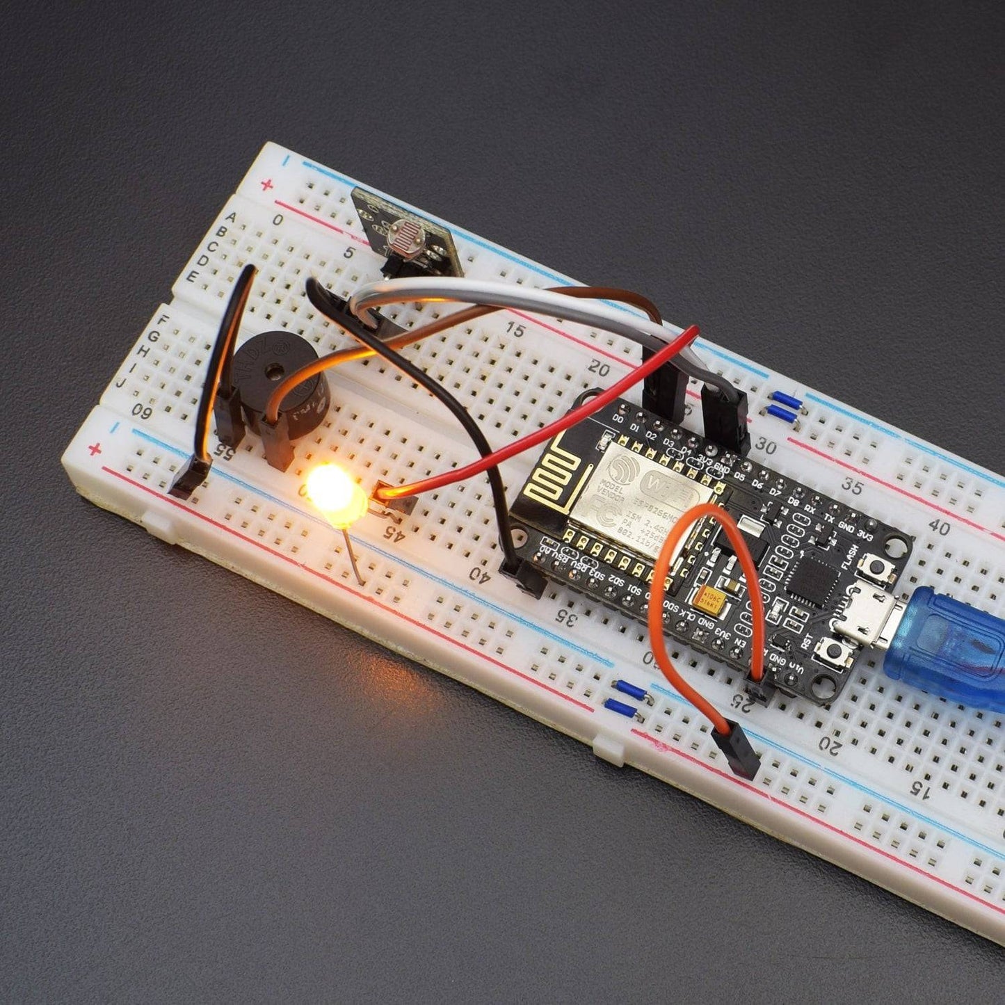
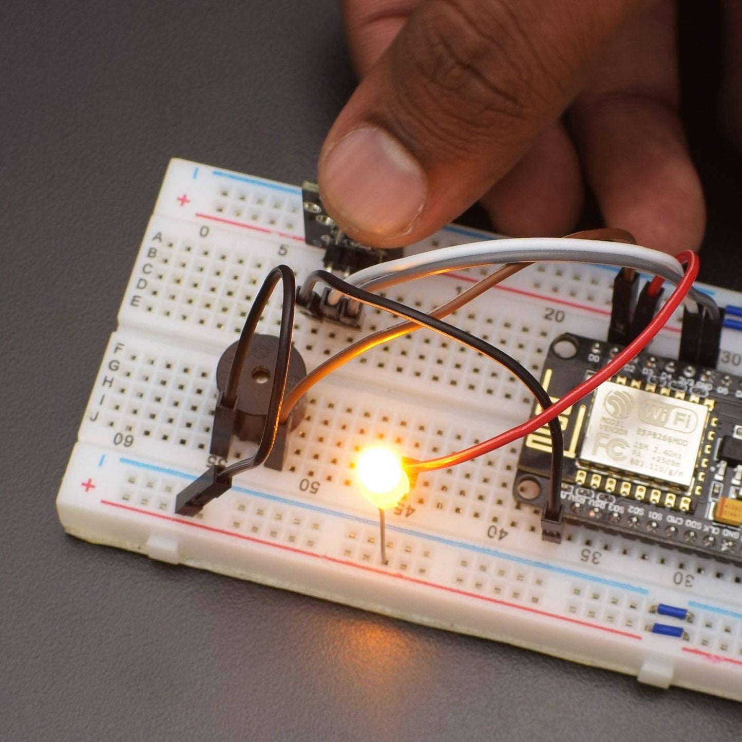
WORKING AND OUTPUT
Welcome to the IoT-based project in which we are using an LDR Module using the ESP8266-12E wifi module. When Light falls upon an LDR Module and exceeds the set value in the code, then the buzzer will start beeping.