


Generic
CD74HC4067 Breakout Board 16-Channel Analog/Digital Multiplexer Breakout Board Module Easy-to-Use Multiplexer Board for Arduino - RS1164
CD74HC4067 Breakout Board 16-Channel Analog/Digital Multiplexer Breakout Board Module Easy-to-Use Multiplexer Board for Arduino - RS1164
SKU:RS1164
116 in stock
Couldn't load pickup availability
- For Bulk Order Click Here
- Need Customer Support?
- Free Delivery Above 999/-
For refund/return/replacement, call us at +91 95995 94520 , +91 95991 22209 or mail us at support@rees52.com
Delivery Time
Delivery Time
- Delivery time with the Express Shipping option is 2-3 working days, and with the Standard Shipping option is 5-6 working days. It varies based on location, reliant on courier services.
- Delivery time if the order item is on Preorder Status is 15-20 working days.
COD (Cash on Delivery)
COD (Cash on Delivery)
- For COD you have to pay extra charges of Rs 350/- before the shipment. (We will share the company QR Code, UPI ID or Account details for the same)
Description:
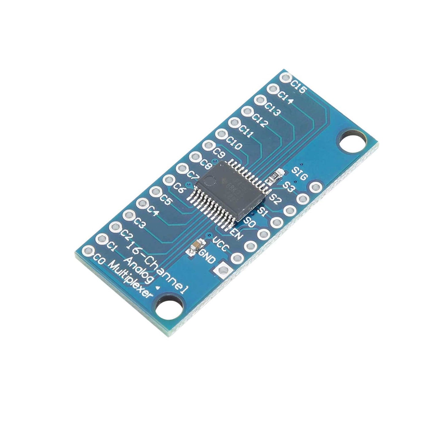
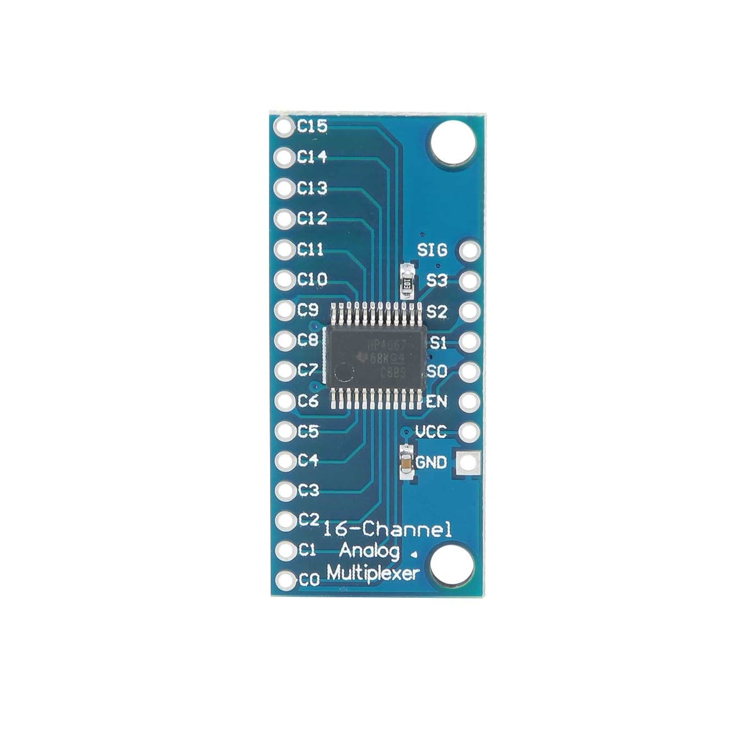
This is a CD74HC4067 16-Channel Multiplexer breakout board that mounts a 74HC4067 which is a 16-channel Analog multiplexer/demultiplexer that can route both analog and digital signals in both directions. 1 of 16 input channels can be routed to 1 output or 1 input can be routed to 1 of 16 output channels.
CD74HC4067 16-Channel Multiplexer can handle analog signals such as from analog sensors or a bank of potentiometers or CD74HC4067 16-Channel Multiplexer can handle digital signals such as from switches, digital sensors or even serial communications. The 74HC4067 can operate over the range of 2 to 6V, so CD74HC4067 16-Channel Multiplexer is compatible with both 3.3 and 5V logic.
CD74HC4067 16-Channel Multiplexer uses binary addressing, so address 0000 is Channel 0, address 1111 is Channel 15. When a channel is ON, CD74HC4067 16-Channel Multiplexer has a resistance of about 70 ohms which allows signals to flow both ways. Maximum current is 25mA through any of the channels.
Specifications:
- Chipset: CD74HC4067
- Channels: 16
- Address Lines: 4
- Supply: 2V to 6V
- On resistance: 70 Ohms @ 4.5V
- 6ns break-before-make @ 4.5V
- Temperature Range: -55C to 125C
Pin Description:
- 1×8 Header Location
- SIG = Signal Input / Output. This will usually connect to an analog input or digital I/O on the microcontroller
- S3 = Binary Address Bit 3. The address bits (3…0) connect to 4 digital output pins on the microcontroller to select channel.
- S2 = Binary Address Bit 2
- S1 = Binary Address Bit 1
- S0 = Binary Address Bit 0
- EN = Enable. Internally pulled LOW to enable by default. Can be pulled HIGH to disable all channels.
- VCC = 2 to 6V. Usually connected to 5V or 3.3V to match the microcontroller power.
- GND = Ground, must be common with the microcontroller.
- 1×16 Header Location
- C15 = Channel 15
- C0 = Channel 0
Package Included:
1 x CD74HC4067 Breakout Board 16-Channel Analog/Digital Multiplexer Breakout Board Easy-to-Use Multiplexer Board for Arduino